HelloDevice Lite Series LS100 User Guide Version 1.4.
User Guide for the HelloDevice LS100 Version 1.4.4 Firmware version 1.4.X Last revised on Dec 12, 2011 Printed in Korea Copyright Copyright 2002-2012, Sena Technologies, Inc. All rights reserved. Sena Technologies reserves the right to make changes and improvements to its product without providing notice. Trademark HelloDevice™ is a trademark of Sena Technologies, Inc. Windows® is a registered trademark of Microsoft Corporation. Ethernet® is a registered trademark of XEROX Corporation.
Contents 1: Introduction 5 1.1 Overview ..................................................................................................................................... 5 1.2 Package Check List .................................................................................................................... 5 1.3 Product Specification................................................................................................................... 6 1.4 Terminologies And Acronyms ..................
.1.2 TCP Server Mode Configuration ..................................................................................... 31 4.2 TCP Client Mode Operations .................................................................................................... 32 4.2.1 Overview ......................................................................................................................... 32 4.2.2 TCP Client Mode Configuration ............................................................................
1: Introduction 1.1 Overview The HelloDevice Lite Series allows you to network-enable a variety of serial devices that were not originally designed to be networked. This capability brings the advantages of remote management and data accessibility to thousands of serial devices over the network. The LS100 is a most cost effective one port serial-Ethernet communication device. The LS100 supports RS232 serial communication allowing virtually any asynchronous serial device to be accessed over a network.
1.
1.4 Terminologies And Acronyms The Internetworking related terminologies used frequently in this manual are defined clearly to help your better understanding of the LS100. MAC address On a local area network or other network, the MAC (Media Access Control) address is the computer's unique hardware number. (On an Ethernet LAN, it's the same as your Ethernet address.
Table 1-1 Acronym Table ISP Internet Service Provider PC Personal Computer NIC Network Interface Card MAC Media Access Control LAN Local Area Network UTP Unshielded Twisted Pair ADSL Asymmetric Digital Subscriber Line ARP Address Resolution Protocol IP Internet Protocol ICMP Internet Control Message Protocol UDP User Datagram Protocol TCP Transmission Control Protocol DHCP Dynamic Host Configuration Protocol SMTP Simple Mail Transfer Protocol FTP File Transfer Protocol PPP Po
2: Getting Started This chapter describes how to set up and configure the LS100 in the first place. - 2.1 Panel Layout explains the panel layout and LED indicators. - 2.2 Connecting The Hardware describes how to connect the power, the network, and the serial device to the LS100. - 2.3 Accessing Console Port describes how to access the console port using a serial console at a local site or telnet console at a remote site. - 2.
Figure 2-1 The panel layout of the LS100 2.2 Connecting The Hardware This section describes how to connect the LS100 to serial device for the first time test. - Connect the power to the LS100 - Connect the Ethernet cable between the LS100 and Ethernet hub or switch - Connect the serial data cable between the LS100 and a serial device 2.2.1 Connecting The Power Connect the power jack to the LS100 power jack using DC power adapter included in the package.
Figure 2-2 Connecting the power to the LS100 2.2.2 Connecting To The Network Connect the one end of the Ethernet cable to the LS100 10Base-T port and the other to the Ethernet network.
2.2.3 Connecting To The Device Connect the serial data cable between the LS100 and the serial device. If necessary, supply the power to the serial device attached to the LS100. Figure 2-4 Connecting a serial device to the LS100 2.3. Accessing Console Port There are two ways to access console port of the LS100 depending on whether the user is located at a local site or a remote site.
2.3.1 Using Serial Console 1) Connect the one end of the serial console cable to the serial port of the LS100. Figure 2-5 Connecting a serial console cable to the LS100 2) Connect the other end of the cable to the serial port of user’s computer. 3) Slide Data/Console switch to Console side. Figure 2-6 Data/Console switch of the LS100 4) Run a terminal emulator program such as HyperTerminal.
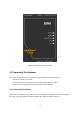
6) Type the user name and password to log into the LS100. A factory default setting of the user name and password are both admin. 7) If the user logged into the LS100 successfully, command prompt screen will appear on the computer as shown in Figure 2-7. login: admin password: ***** Type 'help' to get command usages > help set group par1 [par2 ...] + - group = 'ip','host','serial' or 'admin' - par1 ... = configuration parameters.
1) Run a telnet program or a program that supports telnet functions such as TeraTerm-Pro or HyperTerminal. The target IP address and the port number should be those of the LS100. If required, specify the port number as 23. Type the following command in the command line interface of your computer. telnet 192.168.1.254 Or run a telnet program with parameters as follows. Figure 2-8 Telnet program set up example 2) The user has to log into the LS100. Type the user name and password.
get [group] + Get configuration parameter values - group = 'ip', 'host', 'serial', 'admin' or 'status' - If group is specified, shows settings of the group. - If group is omitted, shows settings of all groups. Parameter value display help [group] + Shows command usage screen. - If group is omitted, shows help screen. - If group is specified, shows 'set' command usage of the group.
next indicates the default gateway IP address. If users want to change only one of the parameters of the group, users can omit trailing parameters and/or can use ‘*’ to keep a parameter value. The screen below will show how to change subnet mask only without changing IP address and gateway IP address. > set ip static * 255.255.0.0 OK > Figure 2-10 Changing only one parameter value example Command usage of ‘set’ will differ depending on the groups.
The group means the category where parameters belong to as like ‘set’ command. For example, if users want to view parameter values related to IP configuration, get command as Figure 2-12 can be used. > get ip IP_mode: static IP_address: 192.168.1.100 Subnet_mask: 255.255.255.0 Gateway: 192.168.1.1 > Figure 2-12 Getting ip configuration screen ‘status’ group is a special group where ‘set’ command does not apply. ‘get status’ will show current system status screen. > get status Serial_no.
2.4.3 ‘help’ Command With ‘help’ command, users can find command usage help in the console screen. Basic command usage is as follows: help [group] + where, if group is omitted, overall help screen will be displayed if group is specified, ‘set’ command usage of specified group will be displayed. Figure 2-15 shows help screen when no group is specified while Figure 2-16 shows help screen with ‘ip’ group specified. > help set group par1 [par2 ...
2.4.4 ‘factorydefault’ Command With ‘factorydefault’ command, users can load factory default parameter values in console. Command usage of ‘factorydefault’ is as follows: factorydefault [option] + where, - if option is omitted, all parameters are set with factory default values. - if option='-ip', all parameters except IP settings are set with factory default values. Loaded values are not saved until ‘save’ command invoked.
2.4.7 ‘reboot’ Command With ‘reboot’ command, the LS100 will be rebooted immediately. Changed parameter values will be applied when the LS100 is up again.
3: IP Address Configuration A valid IP address of the LS100 needs to be assigned before it starts to work in the user's network environment. A network system administrator may provide the user with this IP address setting information for the network. The IP address must be unique within the network. Otherwise, the LS100 will not have a valid connection to the network. Users can choose the desired IP mode out of the three IP operating modes, i.e., Static IP, DHCP and PPPoE.
3.1 Static IP 3.1.1 Overview In the Static IP mode, users have to manually specify all the parameters such as IP addresses of the LS100, valid subnet mask and the default gateway IP address. IP address is an identification number assigned to a computer as a permanent address on the network. Computers use IP addresses to identify and talk to each other on the network. Choose the proper IP address which is unique and valid on the network environment.
> set ip static 192.168.1.10 255.255.255.0 192.168.1.1 OK Figure 3-1 Setting IP configuration parameters for Static IP mode 3.2 DHCP 3.2.1 Overview Dynamic Host Configuration Protocol (DHCP) is a communications protocol that lets network administrators manage and automate the assignment of IP addresses centrally in an organization's network.
3.2.2 DHCP Configuration To make the LS100 work in DHCP mode, just set IP mode to DHCP as in Figure 3-2. > set ip dhcp OK > Figure 3-2 Setting DHCP mode 3.3 PPPoE 3.3.1 Overview PPPoE (PPP over Ethernet) is a specification for connecting multiple computer users on an Ethernet local area network to a remote site through common customer premises equipment, which is the telephone company's term for a modem and similar devices.
3.4 IP Filtering The LS100 has an IP address based filtering feature to prevent unauthorized remote hosts from accessing LS100. The user can allow one of the following scenarios by changing the parameter settings: - Only one host of a specific IP address can access the LS100 - Hosts on the a specific subnet can access the LS100 - Any host can access the LS100 The user may allow a host or a group of hosts to access the LS100. Then the user must enter the IP address and subnet to be allowed for accessing.
4: Host Mode Configuration Host mode represents the operating session mode of the LS100. Several host modes are available for the data communication between the serial device and remote hosts. Since TCP is connectionoriented protocol, server, client, server/client modes are provided. Table 4-1 shows the brief description of the host modes. A factory default host mode is TCP Server.
set host hostmode par1 par2 ...
Sync-Sent If the LS100 sends a connection request to a remote host, the state is changed from [Closed] to [Sync-Sent]. This state is maintained until the remote host accepts the connection request. This state is valid only in TCP client mode. Established It represents “an open connection”. If one of the hosts accepts a connection request from the other host, the connection is opened and state is changed into [Established].
2) Operations Serial data transfer When a session has been established, the LS100 reads the data from the serial port buffer till internal serial buffer is full or inter-character time interval reaches the time specified as intercharacter timeout value. Then, it transfers the data to the IP address of the remote host. If there’s no remote host connected to the LS100, all the incoming data from the serial port are discarded.
4.1.2 TCP Server Mode Configuration To configure the LS100 to work as a TCP server, use ‘set’ command as follows: set host tcps listening_TCP_port inactivity_timeout + where, listening_TCP_port: Listening TCP port Inactivity_timeout: Inactivity timeout in seconds. Listening TCP port is the TCP port number through which remote host can connect a TCP session, and, send and receive data. Incoming connection request to the ports other than Listening TCP Port will be rejected.
4.2 TCP Client Mode Operations 4.2.1 Overview The LS100 works as a TCP client, and the default TCP state is [Closed] in this mode. The remote host will be either Ethernet-Serial communication devices acting as a TCP server or a socket program acting as a TCP server running on users’ PC. 1) Typical State Transition [Closed] --> [Sync-Sent] --> [Established] --> [Data] --> [Closed] At start-up, an initial TCP state is [Closed].
Cyclic Connection It Cyclic Connection function is enabled, the LS100 will make an attempt to connect to the userdefined remote host at certain interval even if there’s no incoming serial data from the device. If the remote host prepares certain data, it will be transferred to the serial device via its serial port after the connection is established.
4.2.2 TCP Client Mode Configuration To configure the LS100 to work as a TCP client, use set command as follows: set host tcpc dest_ip dest_port cyclic_connection_interval inactivity_timeout + where, dest_ip = destination IP address dest_port = destination TCP port cyclic_connection_interval = cyclic connection interval in minutes inactivity_timeout = inactivity timeout in seconds.
[Listen] --> [Sync-Sent] --> [Established] --> [Data] --> [Closed] --> [Listen] The initial state is [Listen]. If there are data coming from the serial port, it will connect to the remote host as a TCP client. If there is incoming connection request from the remote host, it will accept the connection as a TCP server, and then transfer data through the serial port. Thus, users can assume that the LS100 is always connected to the specified remote host.
4.3.2 TCP Server/Client Mode Configuration To configure the LS100 to work as a TCP server/client mode, use ‘set’ command as follows: set host tcpsc listening_port dest_ip dest_port cyclic_connection_interval inactivity_timeout where, listening_port = listening TCP port dest_ip = destination IP address dest_port = destination TCP port cyclic_connection_interval = cyclic connection interval in minutes inactivity_timeout = inactivity timeout in seconds.
5: Serial Port Configuration To attach the serial device to the LS100 serial port, its serial port operation should match exactly to that of the serial device. Serial port configuration parameters are summarized in Table 5-1.
The factory default setting of the flow control is None. Only hardware flow control using RTS/CTS is supported by the LS100. Hardware flow control method controls data communication flow by sending signals back and forth between two connected devices. The purpose of the DTR/DSR pin is to emulate modem signal control or to control TCP connection state by using serial port signal. The DTR is a write-only output signal, whereas the DSR is a read-only input signal in the LS100 side.
> set serial 9600 7 e 2 h s n 10 OK > Figure 5-1 Serial port configuration 39
6: System Administration Users can configure administrator username, password and device name using set command as follows: set admin username password devicename username: login username password: login password devicename: device name Figure 6-1 shows administrative parameters configuration example: > set admin adminuser adminpassword LS100_test1 OK > Figure 6-1 Administration parameters configuration 40
Appendix A: Connections A.1 Ethernet Pinouts The LS100 uses standard Ethernet connector, which is a shielded connector compliant with AT&T258 specifications. Table A-1 shows the pin assignment and the wire color. Figure A-1 Pin layout of the RJ45 connector Table A-1 Pin assignment of the RJ45 connector Pin Description Color 1 Tx+ White with orange 2 Tx- Orange 3 Rx+ White with green 4 NC Blue 5 NC White with blue 6 Rx- Green 7 NC White with brown 8 NC Brown A.
A.3 Ethernet Wiring Diagram HelloDevice Remote Host Tx+(1) Tx-(2) Rx+(3) Rx-(6) Tx+(1) Tx-(2) Rx+(3) Rx-(6) Figure A-3 Ethernet direct connection using crossover ethernet cable HelloDevice Hub Tx+(1) Tx-(2) Rx+(3) Rx-(6) Tx+(1) Tx-(2) Rx+(3) Rx-(6) Remote Host Tx+(1) Tx-(2) Rx+(3) Rx-(6) Tx+(1) Tx-(2) Rx+(3) Rx-(6) Figure A-4 Ethernet connection using straight through ethernet cable A.
Appendix B: Well-known Port Numbers The port numbers are divided into three ranges: the Well Known Ports, the Registered Ports, and the Dynamic and/or Private Ports. The Well Known Ports are those from 0 through 1023. The Registered Ports are those from 1024 through 49151. The Dynamic and/or Private Ports are those from 49152 through 65535. The Well Known Ports are assigned by the IANA, and on most systems, can only be used by system processes or by programs executed by privileged users.
Appendix C: Troubleshooting C.1 Power/LED Status Troubleshooting Problem Cause Action Power LED does not light up Power cable is not connected Check power connection Link LED does not light up Ethernet cable is not connected Check Ethernet cable connection Invalid Ethernet cable is used There are two types of Ethernet cables: Straight-through cable and crossover cable. If you are using an Ethernet hub, use straight-through cable.
Cannot login to console Invalid username and/or Use valid username and password. If username and/or password password are lost, perform factory default reset using factory reset switch. Factory default value of username and password are both admin C.
C.7 Serial Communication Troubleshooting Problem Cause Action Serial data are not Too large inter-character transferred by timeout TCP/IP immediately Set inter-character timeout with smaller value Cannot communicate with the LS100 Invalid serial port configuration Check if serial port configuration of the LS100 are the same with that of the serial device Invalid data transferred Invalid serial port configuration Check if serial port configuration is correct.
Appendix D: Warranty D.1 GENERAL WARRANTY POLICY Sena Technologies, Inc. (hereinafter referred to as SENA) warrants that the Product shall conform to and perform in accordance with published technical specifications and the accompanying written materials, and shall be free of defects in materials and workmanship, for the period of time herein indicated, such warranty period commencing upon receipt of the Product.
D.3 HARDWARE PRODUCT WARRANTY DETAILS WARRANTY PERIOD: SENA warranties embedded hardware Product for a period of one (1) year, and external hardware Product for a period of three (3) or five (5) years according to the Product type. WARRANTY PROCEDURE: Upon return of the hardware Product SENA will, at its option, repair or replace Product at no additional charge, freight prepaid, except as set forth below.