
User Manual
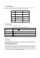


3.2. LED Indicators
Serial-Tx and Serial-Rx LED will flash accordingly when data is transmitted. For small data
transmissions, it may be hard to recognize the quick flashing action of the LED.
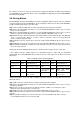
Table 3-2 The Parani-SD1000U LED Indicators
Indicator
Mode LED
Connect LED
Mode 0
Green
┏━━━━━
Mode 1
Green
(every 1 sec) ┏┓
Mode 2
Green
(every 3 sec) ┏┰┓
Mode 3
Green
(every 3 sec) ┏┰┰┓
Connected
Green
(every 1 sec) ┏┓
3.3. Serial Ports
The applicable settings for serial ports are as follows.
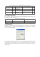
Table 3-3 The Parani-SD1000U Serial Port Settings
Serial Port Settings
Values
Baud rate
1200, 2400, 4800, 9600, 14400, 19200, 38400, 57600, 115200, 230400, 460800,
921600
Data bite
8
Parity
No parity, Even parity, Odd parity
Stop bit
1, 2
Hardware Flow Control
Use, No Use
The values in box are the factory defaults. The flow control setting is configurable only through dip
switch.
3.4. Data Bit
Parani-SD1000U supports only 8 data bit. In the case of 7 data bit and even/odd parity, use SD 8 data
bit and none parity. At this time, master and slave are Parani-SD, Parani-ESD or Parani-MSP series.
But 7 data bit and none parity is not support.
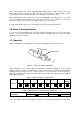
3.5. Hardware Flow Control
Parani-SD1000U plugged into its host system transmits data from host to the other side Bluetooth
device. This data is saved temporarily in the internal buffer of Parani-SD1000U and sent repeatedly
until the transmission is completed packet by packet. When the radio transmission condition is not
good enough to send data promptly, it can cause a transmission delay. If the host sends more data
when the buffer is full, buffer overflow will make Parani-SD1000U malfunction consequently. In order
to prevent this buffer overflow, Parani-SD1000U works as follows.