
User guide

ProBee-ZE20S-SExx User Guide Rev 1.8
41
4 Digital and Analog I/O
4.1 GPIO (General Purpose Inputs and Outputs) Configuration
The ZE20S module has total 18 I/O pins. Among these pins, I/O pin 2 is assigned to factory reset only
and the user can use the rest 17 pins for general purpose inputs and outputs. The I/O pin assignments
are shown in Table 4-1. As shown in Table 4-1, some pins provide special functions built into the firmware.
Table 4-2 describes the special functions tied to the specific pins.
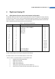
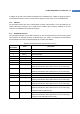
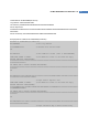
Table 4-1 Default I/O Pin Assignments
Pin Number
GPIO Number
Special Functions AI Enable
2 - Factory reset / Bootloader (SW_0) X
3 0 Permit joining / Wake-up (SW_1) X
4 1 UART_DTR X
5 2 UART_DSR X
6 3 UART_CTS X
7 4 UART_RTS X
8 5
X
9 6
X
10 7
X
11 8
X
32 9
O (AI_0)
31 10
O (AI_1)
30 11
O (AI_2)
29 12
O (AI_3)
28 13
O (AI_4)
27 14
O (AI_5)
24 15 Power LED (LED_0) X
23 16 Status LED (LED_1) X
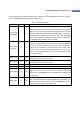
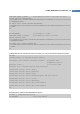
The AT command below can be used to change the GPIO settings.
AT+GPIO=<values><CR> or AT+GPIO<number>=<value><CR>
, where <values> is a number between 0~6 as explained below:
0 Disabled (unmonitored digital input)
1 Digital input, monitored
2 Digital output, default low
3 Digital output, default high
4 Analog input, single ended (only valid for GPIO9~14)
5 Reserved for pin-specific alternate functionalities (See Table 4-2)