
User guide

ProBee-ZE20S-SExx User Guide Rev 1.8
45
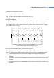
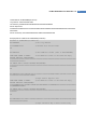
In addition to the data communication via RS232 port, the RS232 port is capable of supplying power to
the development board. In order to use this feature, supply 5V power via the 9
th
pin of the DB9 socket.
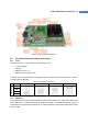
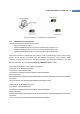
5.3.3 USB Port
The development board also has a USB interface for UART communication. To use the USB port, the
HOST (SW2) switch should be set to USB and the software driver should be installed on the host
computer. The installation CD contains the software.
5.3.4 ZE20S GPIO Interface
The development board’s external GPIO interfaces as well as functional buttons such as factory default
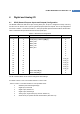
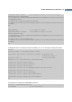
reset switches are internally routed to the ZE20S GPIO pins. Table 5-2 summarizes the development
board’s interfaces and their corresponding GPIO pin numbers of the ZE20S.
Table 5-2 Development Board GPIO Interface Allocation
ZE20S
Pin Number
Name Description
2 Factory Reset Factory Default Reset Switch (SW8)
3 GPIO_0 Permit Joining Switch (SW9)
4 GPIO_1 UART DTR Output
5 GPIO_2 UART DSR Input
6 GPIO_3 UART CTS Input
7 GPIO_4 UART RTS Output
22 H/W Reset Hardware Reset Switch
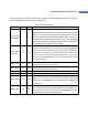
23 GPIO_16 Digital Output with LED(CR19) Display (Active High)
Digital Input with Button Switch (SW17, Active Low or Active High)
24 GPIO_15 Digital Output with LED(CR18) Display (Active High)
Digital Input with Button Switch (SW16, Active Low or Active High)
25 UART_RXD UART Data Input
26 UART_TXD UART Data Output
27 GPIO_14 Digital Output with LED(CR17) Display (Active High)
Digital Input with Button Switch (SW15, Active Low or Active High)
28 GPIO_13 Digital Output with LED(CR16) Display (Active High)
Digital Input with Button Switch (SW14, Active Low or Active High)
29 GPIO_12 Digital Output with LED(CR15) Display (Active High)
Digital Input with Button Switch (SW13, Active Low or Active High)
Analog Input with Light Sensor (U7)
30 GPIO_11 Digital Output with LED(CR14) Display (Active High)
Digital Input with Button Switch (SW12, Active Low or Active High)
Analog Input with Temperature Sensor (U6)