ProBee-ZS10 User Guide Rev.1. 1.1 ZigBee Serial Adapter ProBee-ZS10 User Guide Sena Technologies, Inc. Rev 1.1.
ProBee-ZS10 User Guide Rev.1. 1.1 ProBee-ZS10 User Guide Firmware version PTv1.X Copyright Copyright 2011 Sena Technologies, Inc. All rights reserved. Sena Technologies reserves the right to make changes and improvements to its product without providing notice. Trademark ProBee™ is a trademark of Sena Technologies, Inc. Windows® is a registered trademark of Microsoft Corporation. Ethernet® is a registered trademark of XEROX Corporation.
ProBee-ZS10 User Guide Rev.1. 1.1 Contents 1 2 INTRODUCTION ....................................................................................................... 8 1.1 About This Document ................................................................................................................ 8 1.2 Overview ...................................................................................................................................8 GETTING STARTED.......................................
ProBee-ZS10 User Guide Rev.1. 1.1 4 DATA TRANSMISSION........................................................................................... 27 4.1 4.1.1 Unicast ............................................................................................................................. 27 4.1.2 Multicast ........................................................................................................................... 27 4.1.3 Broadcast ..................................................
ProBee-ZS10 User Guide Rev.1. 1.1 5.4.5 AT+POWER or AT+PW..................................................................................................... 39 5.4.6 AT+STACK or AT+ZS........................................................................................................ 39 5.4.7 AT+NODENAME or AT+NN .............................................................................................. 40 5.5 Network Formation and Join .......................................................
ProBee-ZS10 User Guide Rev.1. 1.1 6 AT COMMAND EXAMPLES ................................................................................... 47 6.1 6.1.1 Coordinator....................................................................................................................... 47 6.1.2 Router .............................................................................................................................. 47 6.1.3 End-device .........................................................
ProBee-ZS10 User Guide Rev.1. 1.1 7.4.3 S53................................................................................................................................... 57 7.4.4 S54................................................................................................................................... 57 7.4.5 S55................................................................................................................................... 58 7.4.6 S56.............................
ProBee-ZS10 User Guide Rev.1. 1.1 1 Introduction 1.1 About This Document This document provides an introduction on configuration and operation of the ProBee-ZS10 ZigBee Serial Adapter. This document assumes the user is using the Z S10 adapter for evaluation hence the pictures and configuration examples shown in this document are all based on the ZS10 adapter. This document does not provide full detail of the hardware specifications.
ProBee-ZS10 User Guide Rev.1. 1.
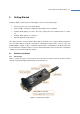
ProBee-ZS10 User Guide Rev.1. 1.1 2 Getting Started Creating a ZigBee network using the ZS10 adapter s consists of the following steps: Connect a power source to the ZS10 adapter Create a ZigBee network by configuring a ZS10 adapter as the coordinator Configure ZS10 adapters as routers. This step is optional since the coordinator works as a router too.
ProBee-ZS10 User Guide Rev.1. 1.1 2.1.2 Connecting the panel Please connect the device to your computer directly or using serial cable so AT commands can be sent from the computer to the ZS10 adapter. The serial port of the panel is DB9 male as a DTE terminal. Figure 2-2 Serial Cable In stallation 2.1.3 Powering the panel Once all the installations are completed, please plug in the power connector using the included DC power adapter. Alternatively, the panel can be powered using battery pack.
ProBee-ZS10 User Guide Rev.1. 1.1 2.1.4 Attaching Battery Pack to ZS10 The ZS10 also supports optional standard battery pack (240mAh) and extended battery pack (900mAh). Attach the battery pack to the ZS10 as shown below to power the ZS10 using the battery pack. To recharge the battery pack, connect the external DC power adaptor as described in Section 2.1.3. Figure 2-4 Attaching Battery Pack to ZS10 2.1.5 Step1.
ProBee-ZS10 User Guide Rev.1. 1.1 Step2. Slide the battery pack into the ZS10 slot. Figure 2-6 Attach the battery pack Step3. Fasten the battery pack to the ZS10. Figure 2-7 Fasten the battery pack 2.2 Configuration 2.2.1 LED RS232-Tx and RS232-Rx LED will flash accordingly when data is transmitted. For small data transmissions, it may be hard to recognize the quick flashing action of the LED. Charge Led and Low battery LED will be off, if you don’t use battery pack.
ProBee-ZS10 User Guide Rev.1. 1.1 blink periodically. Please refer to 7 S-Registers for S14 regarding the management of the LED status. Status Status LED turns ON when the device joins a network, blinks when joining is permitted, and turns OFF when leaves the network. If the node is set to an end-device, it will blink periodically. Please refer to 7 S-Registers for S14 regarding the management of the LED status.
ProBee-ZS10 User Guide Rev.1. 1.1 parity, stop bit and flow control option. If the baud rate needs to a baud rate not shown below, ProBee Manager or terminal program should be used to set these speeds. To set a baud rate not shown below the dipswitches should be in the S/W Config setting. When in the S/W Config setting the baud rate will go back to 9600 as default. Table 2-3 Baud rate Settings by Dipswitches 2400 4800 9600 19.2K 38.4K 57.6K 115.
ProBee-ZS10 User Guide Rev.1. 1.1 Figure 2-9 HyperTerminal Serial Settings To display the AT commands that are being typed, you need to enable the local echo option on the HyperTerminal. To enable this option, Go to File->Properties->Settings->ASCII setup and select the “Echo typed characters locally” option. To verify the connection, type AT and press the Enter key. If the AT command is accepted by the ZS10, OK string will be displayed on the screen.
ProBee-ZS10 User Guide Rev.1. 1.1 2.4 Using ProBee Manager for Configuration Figure 2-11 ProBee Manager It is possible to set or get the configurations of the ZS10 using ProBee Manager. This PC utility helps that a user can configure several setting values easily without a terminal program and upload the firmware file to local and/or remote node.
ProBee-ZS10 User Guide Rev.1. 1.1 3 ZigBee Network Configuration A ZigBee Network consists of a coordinator, routers and end devices. A minimal ZigBee network consists of one coordinator and multiple end devices which directly connect to the coordinator. For larger ZigBee networks, routers are required to provide redundant routings to form mesh networks. ZigBee Coordinator: The coordinator forms the root of the network tree and might bridge to other networks.
ProBee-ZS10 User Guide Rev.1. 1.1 Configure the ZS10 node type as the coordinator Optionally, select the channel mask. Otherwise, the ZS10 will use the default channel mask. Optionally, set up the PAN ID and/or the extended PAN ID. Otherwise, the ZS10 will generate the PAN ID and/or the extended PAN ID automatically. Permit joining when other router or end device tries to join the ZigBee network. 3.1.
ProBee-ZS10 User Guide Rev.1. 1.1 Table 3-2 Channel Bitmask Channel 12 13 14 15 16 17 18 Bit mask 00001000 00002000 00004000 00008000 00010000 00020000 00040000 Channel 19 20 21 22 23 24 25 Bit mask 00080000 00100000 00200000 00400000 00800000 01000000 02000000 3.1.3 PAN ID Configuration for Coordinator Every ZigBee network should be assigned a PAN ID to identify the network. If the PAN ID is 0000, the ZS10 will generate a random 16-bit PAN ID to start the ZigBee network.
ProBee-ZS10 User Guide Rev.1. 1.1 The user can permit joining for a moment at need. The AT command to permit joining is AT+PERMIT= n or AT+PJ=n Where n is the duration to permit in seconds ranging 1~254 seconds. The user can also use the function button to permit joining. When the button pressed, the ZS10 permits joining for the duration that is configured in S-register 22 (S22). The AT command to change the duration is as follows: ATS22=n Where n is the duration to permit in seconds ranging 1~254 seconds.
ProBee-ZS10 User Guide Rev.1. 1.1 Example) AT+NODETYPE=2 # Select router mode OK # Response ATZ # Apply the change OK # Response 3.2.2 Channel Mask Configuration for Router When the ZS10 as a ZigBee router or a ZigBee end device tries to join, it scans all the channels configured by channel mask to find the ZigBee network to join. The channel mask of rout er or end device should include the channel on which the coordinator is operating.
ProBee-ZS10 User Guide Rev.1. 1.1 3.3 Setting up ZS10 as an End Device An end device is a leaf node which communicates only with its parent node and will not relay messages directly. To configure the ZS10 as a ZigBee end device, please follow the steps below. Configure the ZS10 node as an end device Optionally, select the channel mask. Otherwise, the ZS10 will use the default channel mask. Optionally, set up the PAN ID and/or the extended PAN ID.
ProBee-ZS10 User Guide Rev.1. 1.1 the ZigBee network found automatically. Configure the settings for sleep interval. Please refer to the section 3.2 Setting up ZS10 as a Router for the AT commands regarding the node type selection through the PAN ID configurations. One of the unique features of the ZigBee device is its extreme low power consumption which is mainly achieved by its efficient sleep and wake-up mechanism.
ProBee-ZS10 User Guide Rev.1. 1.1 Parent Node S53 S52 Sleep S54 Wake-Up Sleep Sleepy End Device Poll Request Data Exchange Figure 3-1 Sleep Interval and Wake-up Timing The sleepy end device can also wake up from the sleep mode by function button interrupt or incoming serial data. Once it wakes up, it also polls with the parent node at S52 interval and goes into sleep mode after S54 time elapses after the last data exchange.
ProBee-ZS10 User Guide Rev.1. 1.1 3.5.1 Security Level In order to use security in the application, a user should set security level using the AT command below. Set 1 defines both Authentication and Encryption at the network layer. Set 0 defines no security. Disabling security in the application is not ZigBee compliant. All nodes in the network should have the same security level setup. The security level is configured using the AT command below. AT+SECURITY=n, where n is encryption level.
ProBee-ZS10 User Guide Rev.1. 1.1 4 Data Transmission The ZS10 supports three different types of data transmissions: unicast, multicast and broadcast. Unicast is to transmit data to a specific ZigBee device. Multicast is to transmit data to a group of ZigBee devices that are assigned a specific group ID. Broadcast is to transmit data to all ZigBee devices (or specific type of ZigBee nodes if specified) in the network.
ProBee-ZS10 User Guide Rev.1. 1.1 ATS36=n, where n is the radius. ATS37=n, where n is the number of hops through nonmembers. 4.1.3 Broadcast Broadcast transmissions are sent from a source device to all devices in the ZigBee network. The AT command for the broadcast transmissions is as below. AT+BROADCAST= Where = data to transmit The user can also specify the transmit range by changing the S35 register value as below. Please refer to the 7 S-Registers for more details.
ProBee-ZS10 User Guide Rev.1. 1.1 the data mode, on the other hand, incoming data is always displayed. To change the S11 register, please use the AT command as below: ATS11=, where = 0 to hide incoming message, 1 to show incoming message. If user wants to display incoming message in command mode, S11 should be enabled. It is presented by a form of +|.
ProBee-ZS10 User Guide Rev.1. 1.1 ATD Set unicast data mode to the preconfigured destination IEEE address without reset. ATD Set unicast data mode and can be either 16-bit node ID or 64-bit IEEE address of remote node. AT+TRANSMITMODE=1 Set the transmit mode to unicast to a destination IEEE address. The device should be reset to apply the mode. AT+TRANSMITMODE=4 Set the transmit mode to unicast to a sink node. A sink node is determined if s-register 61 is set.
ProBee-ZS10 User Guide Rev.1. 1.1 AT+TRANSMITMODE=1 # Set transmit mode to destination IEEE address OK # Response ATZ # Apply to change OK # Response Send unicast msg # Put the unicast message +++ # Leave data mode OK # Response AT+TRANSMITMODE=4 # Set transmit mode to sink node in the network OK # Response ATZ # Apply to change OK # Response Send unicast msg # Put the unicast message +++ # Leave data mode OK # Response 4.2.
ProBee-ZS10 User Guide Rev.1. 1.1 Set multicast data mode to preconfigured destination group ID without reset. ATM Set multicast data mode and can be 16-bit group ID. AT+TRANSMITMODE=2 Set the transmit mode to multicast mode. The device should be reset to apply the mode. ATS36=n, where n is the radius. ATS37=n, where n is the number of hops through nonmembers. Set data relay and forwarding options. Please refer to the 7 S-Registers for more details.
ProBee-ZS10 User Guide Rev.1. 1.1 4.2.3 Broadcast Data Mode Broadcast data mode can be used for continuous data transmission to all devices in the current network. The destination address or group ID of the remote nodes is not necessary for broadcast data mode. The transmit range is determined by the S-register 35. Broadcast data mode can be entered using either ATB or AT+TRANSMITMODE=3.
ProBee-ZS10 User Guide Rev.1. 1.
ProBee-ZS10 User Guide Rev.1. 1.1 5 AT Command Reference 5.1 Command Line Format Each command line is composed of a prefix, body and terminator. Only “AT” can be used for the prefix. The body is a string of characters. The terminator is or .
ProBee-ZS10 User Guide Rev.1. 1.1 5.2.4 ATE Description Echo(1) or No Echo(0). Execute ATE Response OK 5.2.5 ATM Enter the multicast mode. If there’s no argument after the command, it will connect to Description the preconfigured destination group ID. Every data is packetized at intervals of inter character timeout(S12). Execute ATM Response OK 5.2.6 ATM ATO Description Return to data mode. Execute ATO Response 5.2.
ProBee-ZS10 User Guide Rev.1. 1.1 5.2.11 +++ Description Interrupt data mode. “+++” must be entered within 500ms. Execute +++ Response OK 5.3 Node Specific Information 5.3.1 AT+LONGADDR or AT+LA Get the 64-bit IEEE address. (EUI address, long address) The IEEE address is a Description unique device address assigned during manufacturing. This address is unique to each physical device. Execute AT+LONGADDR? Response 5.3.
ProBee-ZS10 User Guide Rev.1. 1.1 5.3.5 AT+OPPANID or AT+OI Get the operating 16-bit PAN ID. If PAN ID is set specific value not 0s, operating PAN Description ID will equal designated PAN ID. A value of “FFFF” means the device is not joined a network. Execute AT+OPPANID? Response 5.3.6 OK AT+OPEPID or AT+OE Description Execute Get the operating 64-bit extended PAN ID. A value of “FFFFFFFFFFFFFFFF” means the device is not joined a network. AT+OPEPID? Response 5.3.
ProBee-ZS10 User Guide Rev.1. 1.1 Range 5.4.2 00001000 - 03FFF000 AT+PANID or AT+PI Get/Set the 16-bit PAN ID. If it is set to 0s, the coordinator will select a random 16-bit Description hexadecimal number as PAN ID, and the router/end-device will join any existing network if it is allowed. Execute AT+PANID? Response OK Default 0000 Range 0000 – FFFF 5.4.3 OK or ERROR AT+EPID or AT+EI Description Execute Get/Set the 64-bit extended PAN ID.
ProBee-ZS10 User Guide Rev.1. 1.1 that should join the same network. (0: Network specific, 1: ZigBee, 2: ZigBee Pro) Execute AT+STACK? Response OK Default 0 Range 0-2 5.4.7 AT+STACK= OK or ERROR AT+NODENAME or AT+NN Description Execute Get/Set the node name. It can be used to make a clear distinction role or functionality of local node from others. AT+NODENAME? Response OK Default ProBee-ZS Range Up to 16 characters 5.
ProBee-ZS10 User Guide Rev.1. 1.1 AT+DSCAN= or AT+DSCAN=, or AT+DSCAN=,, ||||| Response List of the existing nodes and information… OK Scan duration: 1 – 10 Range 5.5.4 Node type: 0 – 4 (Zero indicates all node types.) AT+NODETYPE or AT+NT Description Execute Get/Set the node type.
ProBee-ZS10 User Guide Rev.1. 1.1 Response 5.6.3 OK AT+PARENTSA or AT+PS Description Get the 16-bit Node ID of the parent node. Execute AT+PARENTSA? Response 5.6.4 OK AT+CHILDTABLE or AT+CT Description Get the child table composed of the end-devices. Execute AT+CHILDTABLE? || Response List of the child nodes… OK 5.7 Data Transmission and Reception 5.7.
ProBee-ZS10 User Guide Rev.1. 1.1 5.7.4 AT+MAXPAYLOAD or AT+MP Description Execute accept. The size depends on the security level in use. AT+MAXPAYLOAD? Response 5.7.5 Get the maximum size of the payload that the Application Support sub-layer will OK AT+TRASNSMITMODE or AT+TM Get/Set the data transmission mode. This mode is maintained after rebooting.
ProBee-ZS10 User Guide Rev.1. 1.1 available remote command by “AT+REMOTE”. Execute AT+REMOTE=,? Response OK 5.8 UART 5.8.1 AT+BAUDRATE or AT+UB Description Execute host. OK Default 9600 Range 300 - 230400 5.8.
ProBee-ZS10 User Guide Rev.1. 1.1 5.8.5 AT+FLOWCTRL or AT+UF Description Get/Set flow control status. (0: none, 1: software, 2: hardware flow control) Execute AT+FLOWCTRL? Response OK Default 2 Range 0-2 5.9 Security 5.9.1 AT+SECURITY or AT+SE Description Execute the same security level in the network. OK Default 0 Range 0-1 5.9.2 OK or ERROR Get/Set the security status.
ProBee-ZS10 User Guide Rev.1. 1.1 Response 5.10 OK or ERROR Firmware Upload and Help 5.10.1 AT+BOOTLOAD or AT+BL Start bootloader to upload firmware. (blank: local, 1: passthru, 2: clone) The device leaves the AT command line and enters the bootloader menu for uploading Description new ProBee firmware. There’s no restrict to use local upload but a sleepy end device cannot upload to remote node over the air.
ProBee-ZS10 User Guide Rev.1. 1.1 6 AT Command Examples 6.1 Network configuration 6.1.1 Coordinator AT+NODETYPE=1 # set node type (coordinator) OK # Response ATZ # Apply the change OK # Response 6.1.2 Router AT+NODETYPE=2 # set node type (router) OK # Response ATZ # Apply the change OK # Response 6.1.3 End-device AT+NODETYPE=3 # set node type (end-device) OK # Response ATZ # Apply the change OK # Response 6.1.
ProBee-ZS10 User Guide Rev.1. 1.1 00019500002FDC15 OK # Response AT+REMOTE=1FEF,AT+LONGADDR # get 64-bit address of remote node (1FEF) 00019500002FDC15 OK # Response AT+DSCAN # get the information of other nodes in the network ZC |00019500002FDC40|0000|PTv1.0|ZE10|Z E10_COM3 ZR |00019500002FDC15|1FEF|PTv1.0|ZE10|Z E10_COM4 CLD0|00019500002FDC17 CLD1|00019500002FDC14 ZED*|00019500002FDC17|7E34|PTv1.0|ZS10|ZS10_COM5 SED |00019500002FDC14|F5AC|PTv1.0|ZU10|Z U10_COM6 OK # Response 6.
ProBee-ZS10 User Guide Rev.1. 1.
ProBee-ZS10 User Guide Rev.1. 1.1 6.4 Security AT+SECURITY=1 # set security level (ON) OK # Response AT+LINKKEY=5A46…21 # set the 128-bit trust center link key (5A46…21) ATZ # Apply the change OK # Response AT+NWKKEY=0 # set the 128-bit network key (random key) OK # Response AT+UPDATEKEY # update the changed network key OK # Response 6.5 Firmware Upload 6.5.1 Local Node # enter the bootloader menu for uploading firmware.
ProBee-ZS10 User Guide Rev.1. 1.1 6.5.3 Clone # clone the firmware of the local node to a remote node using 64 -bit long address. Note that UART of local node should be set to 115200-8- N-1-N. AT+BOOTLOAD=2,00019500002FDC40 Start cloning ...
ProBee-ZS10 User Guide Rev.1. 1.
ProBee-ZS10 User Guide Rev.1. 1.1 7.1.2 S12 Description Get/Set the command echo mode. Execute ATS12? Response OK Default 1 Range 0–1 7.1.3 OK S13 Description Get/Set the command responses mode. Execute ATS13? Response OK Default 1 Range 0-1 7.1.4 ATS12= ATS13= OK S14 Get/Set the LED mode. It causes the LED operation of ZS10 Description 0: LEDs are always OFF regardless of configuration or status.
ProBee-ZS10 User Guide Rev.1. 1.1 7.2.2 S22 Get/Set the timeout to permit joining. It determines the time in seconds that the device Description will allow other devices to join to it when it starts network but an end-device cannot perform it. If set to 255, the device will always permit joining. Execute ATS22? Response OK Default 60 Range 0 - 255 7.2.3 ATS22= OK S23 Get/Set the power boost mode of the adapter.
ProBee-ZS10 User Guide Rev.1. 1.1 Range 7.3.3 0 – 99 S33 Description Execute Get/Set the transmission timeout in milliseconds. If application-ACK is enabled, a sender retransmits data packet after this time. ATS33? Response OK Default 500 Range 0 – 10000 7.3.4 OK S34 Description Execute Get/Set the indirect transmission timeout in milliseconds. It is the maximum amount of time that the MAC will hold a message for indirect transmission to a child.
ProBee-ZS10 User Guide Rev.1. 1.1 converted to maximum value(30). It is used to multicast/broadcast. Execute ATS36? Response OK Default 0 Range 0 – 10 7.3.7 ATS36= OK S37 Get/Set the number of hops that the message will be forwarded by devices that are not Description members of the group. A value of zero, 7 or greater is treated as infinite. There is no longer a separate limited multicast API call.
ProBee-ZS10 User Guide Rev.1. 1.1 device does not send a poll request to its parent coordinator or router within the poll timeout, the end device is removed from the child table. Execute ATS51? Response OK Default 60 Range 0 – 4177920 7.4.2 OK S52 Description Execute Get/Set the sleepy end device poll period in milliseconds. Adaptive polling may allow the sleepy end device to poll more rapidly for a short time when receiving RF data.
ProBee-ZS10 User Guide Rev.1. 1.1 7.4.5 S55 Get/Set the rejoin timeout . If it is enabled, an end-device tries to rejoin the current Description network when contact with the network has been lost for setting value in seconds. The most common usage case is when an end device can no longer communicate with its parent and wishes to find a new one. Execute ATS55? Response OK Default 10 Range 0 – 10000 7.4.
ProBee-ZS10 User Guide Rev.1. 1.
ProBee-ZS10 User Guide Rev.1. 1.1 8 Mechanical Drawings 8.1 ProBee-ZS10 mechanical drawing (mm) 99.8 with stub antenna 73.9 without antenna 14.9 16 20 30.
ProBee-ZS10 User Guide Rev.1. 1.1 8.
ProBee-ZS10 User Guide Rev.1. 1.1 9 Warranty 9.1 GENERAL WARRANTY POLICY Sena Technologies, Inc. (hereinafter referred to as SENA) warrants that the Product shall conform to and perform in accordance with published technical specifications and the accompanying written materials, and shall be free of defects in materials and workmanship, for the period of time herein indicated, such warranty period commencing upon receipt of the Product.
ProBee-ZS10 User Guide Rev.1. 1.1 external hardware Product for a period of three (3) or five (5) years according to the Product type. WARRANTY PROCEDURE: Upon return of the hardware Product SENA will, at its option, repair or replace Product at no additional charge, freight prepaid, except as set forth below. Repair parts and replacement Product will be furnished on an exchange basis and will be either reconditioned or new. All replaced Product and parts become the property of SENA.
ProBee-ZS10 User Guide Rev.1. 1.1 10 Regulatory Information 10.1 FCC FCC Rule: Part 15 Subpart C Section 15.247 FCCID: S7AZBLINXZS10 FCC Compliance Statement This device complies with part 15 of the FCC Rules.
ProBee-ZS10 User Guide Rev.1. 1.1 ProBee-ZS10 ZigBee Serial Adapter to which this declaration relates is in conformity with the following standard(s) or other normative document(s) EN 60950-1 ETSI EN 301 489-1 ETSI EN 301 489-17 ETSI EN 300 328 Following the provisions of EMC DIRECTIVE 1999/5/EC 10.3 TELEC Technical Regulations for Specified Radio Equipment Article 2, Section 1 (19) Certification No: 010WWBT31 10.
ProBee-ZS10 User Guide Rev.1. 1.1 11 RF Information Radio Frequency Range 2.410~2.475GHz Number of Frequency Channel 14 channels Transmission Method DSSS (Direct Sequence Spread Spectrum) Modulation Method O-QPSK (Offset Quadrate Phase Shift Keying) Radio Output Power +18dBm Receiving Sensitivity -102dBm Power Supply DC3.