USER’S GUIDE Table of Contents: Introduction........................................................2 Precautions.........................................................3 Box Contents.....................................................3 Overview........................................................4-9 Getting Started.........................................10-12 Basic Operation........................................ 13-18 Setting Input Levels......................................
Thank you for choosing Senal. The Senal AWS-2000 is a versatile, lightweight, yet rugged wireless system that is ideal for a wide variety of professional uses such as ENG, interviews, conferences, lectures, and live theater production. The included AWS-2000T beltpack transmitter, AWS-2000R camera mount receiver, and optional AWS-2000P plug-on transmitter have an operating range of up to 500 feet.
Precautions • Please read and follow these instructions, and keep this manual in a safe place. • Keep this unit away from water and any flammable gases or liquids. • Use only the correct, recommended voltage. • Do not attempt to disassemble or repair the equipment—doing so will void the warranty, and Senal will not be responsible for any damage. • Clean the units with only a soft, dry cloth. • Use only parts, accessories, and attachments provided by the manufacturer.
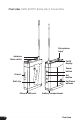
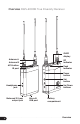
Overview AWS-2000T Body-Pack Transmitter Microphone input Antenna Mute switch OLED display Power button IR port Set button Up/Down buttons Belt clip Micro-B USB port ▪ ▪ ▪ ▪ 4 ▪ ▪ ▪ ▪ ▪ ▪ ▪ ▪ ▪ ▪ ▪ ▪ ▪ ▪ ▪ ▪ ▪ ▪ ▪ ▪ ▪ ▪ ▪ ▪ ▪ ▪ ▪ ▪ ▪ ▪ ▪ ▪ ▪ ▪ ▪ Battery compartment ▪ ▪ ▪ ▪ ▪ ▪ ▪ ▪ ▪ ▪ ▪ ▪ ▪ ▪ ▪ ▪ ▪ ▪ ▪ ▪ ▪ ▪ ▪ ▪ ▪ ▪ ▪ Overview
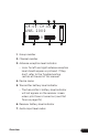
1 2 3 GR.06-CH.08 AWS-2000 MIC LC PLT 4 5 6 7 8 L 9 10 1. Group number 2. Channel number 3. Transmission power indicator 4. Device name 5. Low cut filter 6. Input level indicator 7. Pilot tone indicator 8. Lock indicator 9. Battery level indicator 10.
Overview AWS-2000R True Diversity Receiver OLED display Antenna A Antenna B RF indicator AFS button IR port Peak indicator Power button Set button Up/Down buttons Headphone jack Balanced 3.
1 2 3 GR.06-CH.08 AWS-2000 T R 4 5 6 7 1. Group number 2. Channel number 3. Antenna reception level indicator • Icons for left and right antenna reception level should appear as pictured. If they don’t, refer to the Troubleshooting section at the end of this manual. 4. Device name 5. Transmitter battery level indicator • The transmitter’s battery level indicator will not appear on the receiver screen unless pilot tone is turned on (see Pilot Tone on page 25). 6. Receiver battery level indicator 7.
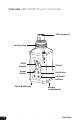
Overview AWS-2000P Plug-On Transmitter XLR connector Locking ring OLED display IR port Power button Set button Up/Down buttons Micro-B USB port ▪ ▪ ▪ ▪ 8 ▪ ▪ ▪ ▪ ▪ ▪ ▪ ▪ ▪ ▪ ▪ ▪ ▪ ▪ ▪ ▪ ▪ ▪ ▪ ▪ ▪ ▪ ▪ ▪ ▪ ▪ ▪ ▪ ▪ ▪ Battery compartment ▪ ▪ ▪ ▪ ▪ ▪ ▪ ▪ ▪ ▪ ▪ ▪ ▪ ▪ ▪ ▪ ▪ ▪ ▪ ▪ ▪ ▪ ▪ ▪ ▪ ▪ ▪ ▪ ▪ ▪ ▪ ▪ Overview
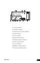
1 2 3 GR.06-CH.08 AWS-2000 MIC 48V LC PLT 4 5 6 7 8 9 L 10 11 1. Group number 2. Channel number 3. Transmission power indicator 4. Device name 5. Low cut filter 6. Input level indicator 7. Phantom power indicator 8. Pilot tone indicator 9. Lock indicator 10. Battery level indicator 11.
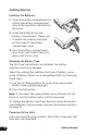
Getting Started Installing the Batteries 1. Open the battery compartment by sliding the battery compartment door in the directions indicated by the arrow. 2. Install the batteries into the battery compartment. Make sure to match the polarity indicated on the inside of the battery compartment door. 3. Press the battery compartment door down, and slide it back into place until it locks shut. Selecting the Battery Type The first time the batteries are installed, the battery selection window will appear.
The battery icon indicates the battery level. The icon blinks to indicate a critically low battery level. Attaching the Antennas Screw the antennas clockwise into the threaded antenna sockets. Make sure they are tightly attached. Connecting the Receiver The AWS-2000 microphone system includes two output cables for devices with an XLR input or a 3.5 mm TRS input. The output cables feature right-angled locking 3.
Mounting the Receiver To use the AWS-2000 as a shoemounted wireless system mounted on a camera, follow these steps: Camera Mount (for Use with One Receiver) 1. Align the camera mount with the back of the AWS-2000R receiver. Press it onto the receiver until it snaps into place. 2. Loosen the locking ring by turning it counterclockwise, and slide the mounting foot into your camera’s shoe mount. 3. Tighten the locking ring by turning it clockwise until . it’s secure.
Basic Operation Power Button • Press and hold to power the unit on and off. • In menu mode, press to return to the main screen. • In the advanced menu, press to return to the main menu. • Double-press to toggle main and headphone output control function of the Up/Down buttons . (Receiver only). See Setting Output Levels on page 20. Set Button SET • Press and hold to enter menu mode. • Press to select a menu item in order to change its value.
Auto Frequency Scanning (AFS) 1. Power on the receiver and transmitter. 2. Press and hold the AFS button on the receiver to initiate a frequency scan. The receiver will scan all available frequencies and select one that is free of interference, [ SCANNING ] will appear on the screen. Once the scan is complete, . [ SYNC >>> ] will appear on the screen, and the receiver will automatically send out a sync signal from its IR port. 3. Position the transmitter and receiver so their IR ports face each other.
4. Press the Up/Down buttons until [ SYNC YES ] appears on the screen. Press Set to being syncing. 5. Position the receiver’s IR port so it faces the transmitter’s IR port. This will sync the transmitter to the frequency from the receiver. [ SYNC ] will appear on the receiver’s screen when the devices have been successfully synced. 6. When syncing is complete, confirm that the receiver and transmitter are tuned to the same channel. If [ SYNC ERROR! ] appears on the screen, repeat the previous steps.
4. Use the Up/Down buttons to select the group number, and press the Set button to store it. The channel number will flash. 5. Scroll to the desired channel number, and press Set to store it. The receiver will automatically prompt you to sync the system. 6. With [ SYNC ] on the screen, press the Set button. The . Yes/No prompt will flash on the screen. 7. Press the Up/Down buttons until [ YES ] flashes on the screen, and press the Set button. The sync indicator arrow will show on the screen. 8.
6. With [ SYNC ] on the screen, press the Set button. . The Yes/No prompt will flash on the screen. Use the Up/ Down buttons until [ YES ] flashes on the screen, and press the Set button. The sync indicator arrow will show on . the screen. 7. Make sure the Transmitter’s and the Receiver’s IR ports are facing each other until [ SYNC ] appears on the screen of the device that’s initiating the sync. 8. When syncing is complete, confirm that the receiver and transmitter are tuned to the same channel.
Lock • Locked disables all of the buttons to prevent accidental changes to the settings. • On w/Level locks all functions except the output level control (Up/Down buttons). Use this setting for quick access to output level changes without changing any of the other settings. • Unlock restores the functions of all the buttons. To change the lock setting, follow these steps: 1. Press and hold the Set button to enter menu mode. 2. Scroll to the [ LOCK ] menu, and press the Set button.
Setting Input Levels AWS-2000T Transmitter and AWS-2000P Plug-On Transmitter The transmitter and plug-on transmitter can be set to MIC or LINE input. • Select [ LINE ] when sending a line-level signal from devices such as a mixer or playback device. Selecting . [ LINE ] sets the input level to a fixed line level. • Select [ MIC ] when connecting a microphone to the transmitter. Selecting [ MIC ] allows you to adjust the input level from -15 to 0 dB on the transmitter, or .
Setting Output Levels AWS-2000R Receiver Main Output The main output controls the signal level that is sent to the input device (camera or recorder) via the 3.5 mm jack on the bottom of the AWS-2000R receiver. 1. Use the Up/Down buttons to adjust the output. The Screen will read [ MAIN OUT ] along with the output level . [ -29 db ] to [ 8 dB ]. 2. Press the Set button to save the change. Set the output level so the input device receives a high signal level without distorting.
2. Use the Up/Down buttons to adjust the headphone output. The screen will read [ PHONE OUT ] along with the output level [ -29 db ] to [ 8 dB ]. 3. Press the Set button to save the change. After approximately 7 seconds, the Up/Down buttons will return to control the main output. Note: Double-pressing the power button will toggle to control the main output level if the Up/Down buttons are preset to control the headphone output (see Headphone Output below).
3. In the advanced menu, scroll to [ OUTPUT ], and press the Set button. The menu selection will blink. 4. Use the Up/Down buttons to scroll to [ TOG LOCK ], and press the Set button. 5. When you have returned to the main screen, double-press the power button to open the output menu. Use the Up/ Down buttons to select [ MAIN ] or [ PHONE ], and press the Set button. The Up/Down buttons are now permanently set to control the output of the desired selection.
Input Level The Up/Down buttons control the input level from . [ -15 db ] to [ 0 dB ] on the transmitter or [ -30 db ] to [ 0 dB ] on the plug-on transmitter. Lock To lock the transmitter to prevent accidental changes to the output level, follow these steps: 1. Press and hold the Set button to enter menu mode. 2. Scroll to [ LOCK ], and press the Set button. The menu selection will blink. 3. Use the Up/Down buttons to select [ LOCKED ], and press the Set button to save your selection.
▪ 4. Use the Up/Down buttons to select between [ LATCH ], . [ OFF ], or [ MOMENTARY ], and press the Set button to save your selection. 5. When muted, [ MUTE ] will appear in place of the audio input level meter. Mute (AWS-2000P Plug-On Transmitter) Double-press the power button to automatically mute the transmitter in latch mode. GR.06-CH.08 AWS-2000 MIC LC PLT Double-press again to resume transmission.
Advanced Functions Receiver Squelch The squelch circuit prevents unwanted interference from compromising your audio. If the signal falls below a certain level, the output of the receiver is muted. Squelch should be set at a level that is slightly above the level of audible interference. Note: A high squelch setting requires a strong signal from the transmitter. Since the transmitter signal strength decreases with distance, a high squelch setting will decrease the range of your wireless system.
Important! In order for pilot tone to protect against interference, the pilot tone option must be activated on both the transmitter and the receiver. To activate pilot tone, follow these steps: 1. Press and hold the Set button to enter menu mode. 2. Scroll to [ ADVANCED MENU ], and press the Set button. 3. In the advanced menu, scroll to [ PILOT ], and press the Set button. The menu selection will blink. 4. Use the Up/Down buttons to select [ ON ].
Main Output The receiver is capable of sending a balanced mic- or linelevel output signal to devices with XLR inputs or 3.5 mm mini-plug inputs. To set the output signal: 1. Press and hold the Set button to enter menu mode. 2. In menu mode, scroll to [ MAIN OUT ], and press the Set button. The menu selection will blink. 3. Use the Up/Down buttons to set the output level for your input device [ -29 db ] to [ 8 dB ]. 4. Press the Set button to confirm the setting.
AWS-2000T Transmitter and AWS-2000P Plug-On Transmitter Pilot Tone For a description of pilot tone, see page 25. Important! In order for pilot tone to protect against interference, the pilot tone option must be activated on the transmitter AND the receiver. To activate pilot tone, follow these steps: 1. Press and hold the Set button to enter menu mode. 2. Scroll to [ ADVANCED MENU ], and press the Set button. 3. In the advanced menu, scroll to [ PILOT ], and press the Set button.
4. Use the Up/Down buttons to select [ ON ]. Press the Set button to save the setting and activate the low-cut filter. When [ LO CUT ] is active, [ LC ] is displayed on the transmitter’s screen. To turn off the low-cut filter, select [ OFF ] in the . [ LO CUT ] menu. Mute For instructions on setting the mute button function, . see Mute (Transmitter) on page 23 and Mute (Plug-On Transmitter) on page 24.
Common Advanced Functions (AWS-2000R Receiver, AWS-2000T Transmitter, and AWS-2000R Plug-On Transmitter) Name Naming the units makes them easy to identify. This is useful when working with several pairs of transmitters and receivers on a production or shoot. To change the name of the unit, follow these steps: Note: Changing the name can be done on either the transmitter or receiver. 1. Press and hold the Set button to enter menu mode. 2. Scroll to [ ADVANCED MENU ], and press the Set button. 3.
If [ SYNC ERROR! ] appears on the screen, the name selection will be saved on the renamed device. To sync the name with the other device, follow the steps for performing a manual sync on page 15. Brightness This menu selection controls the brightness of the characters on the screen. 1. Press and hold the Set button to enter menu mode. 2. In the menu mode, scroll to [ BRIGHTNESS ]. Press Set to enter the menu. The brightness level will blink. 3. Use the Up/Down buttons to select the level.
Restoring the Factory Presets To restore all factory presets, follow these steps: 1. Press and hold the Set button to enter menu mode. 2. Scroll to [ ADVANCED MENU ], and press the Set button. 3. In the advanced menu, scroll to [ RESET ]. 4. Press the Set button. [ RESET??? ] will appear on . the screen. 5. Press Set, and the menu selection will blink. 6. Use the Up/Down buttons to choose [ YES ], and press the Set button to reset the factory defaults.
Frequency Chart AWS-2000A (522 to 554 MHz) Gr. 1 Ch. 1 Gr. 2 523.025 522.725 Gr. 3 Gr. 4 Gr. 5 Gr. 6 Gr. 7 522.800 522.925 522.650 523.550 523.750 Gr. 8 Gr. 9 Gr. 10 523.850 523.950 523.000 Ch. 2 525.475 523.450 526.000 525.375 525.100 526.650 525.500 527.625 526.100 Ch. 3 526.875 526.475 529.100 529.250 527.375 528.500 527.825 528.400 529.375 531.175 524.050 Ch. 4 529.475 530.925 530.150 534.225 533.950 532.200 529.500 537.200 530.250 531.375 Ch. 5 532.425 532.350 533.
Problem Solution One of the antenna reception indicators is always off. This indicates that one of the antennas is not operating correctly. Replace the antenna on the side of the missing level indicator. Note: The receiver will operate with only one antenna, but it will no longer operate as a true-diversity receiver. You will run a greater risk of interference or dropouts. The receiver or the transmitter won’t operate. LOCKED appears on the screen.
Specifications AWS-2000T Transmitter Reference input level -26 dBV Frequency response 80 Hz to 15 kHz Signal-to-noise ratio <100 dB Pilot tone frequency 32.768 kHz Power requirement 2.0 to 3.6 V Operating temperature 32°F to 131°F (0°C to 55°C) Dimensions without antenna (H × W × D) 2.8 × 2.3 × 0.8 in. (7 × 5.08 × 2 cm) Weight 3 oz. (84 g) AWS-2000R Receiver Frequency response 80 Hz to 15 kHz Total harmonic distortion <0.9% Pilot tone frequency 32.768 kHz Power requirement 2.0 to 3.
One-Year Limited Warranty This Senal product is warranted to the original purchaser to be free from defects in materials and workmanship under normal consumer use for a period of one (1) year from the original purchase date or thirty (30) days after replacement, whichever occurs later.