
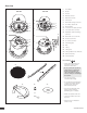
User Manual


4
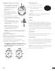
Wiring Schemes
The removable locking connector has four terminals. The pin
function of each terminal is listed on the label located on the
speaker.
Pins 2 and 3 are the “+” and “-” inputs of the speaker, and they are
looped inside the speaker to pins 1 and 4 (Pin 1 connects to Pin 2,
and Pin 3 connects to Pin 4.) Pins 1 and 4 are designed as loop-
through connections to successive speakers.
Parallel wiring
The advantage of this wiring scheme is that when the connector is
pulled out of an individual speaker, the following speakers will remain
connected. This wiring scheme is useful when troubleshooting
because you can disconnect one speaker at a time from the system
without disabling successive speakers. In this scheme pins 1 and 4
have no wires in them.
1. Insert both “+” wires into pin 2 (one wire from the amplifier or the
previous speaker; the other wire to the positive terminal of the
next speaker.)
2. Insert both “-” wires into pin 3 (one wire from the amplifier or
previous speaker; the other wire to the negative terminal of the
next speaker.)
3. Make sure both screw-down terminals are securely tightened.
Note: Because there are two wires connecting to each terminal, it
is important to make sure that the proper contact has been made
and that both wires are securely connected with the screw-down
terminal.
4. Tighten the empty screw-down terminals of pins 1 and 4 to avoid
unwanted vibration.
Loop-through wiring
In this scheme, the subsequent speakers are connected via pins 1 “+”
& 4 “-“. When one speaker is disconnected, all successive speakers
are disconnected too. This scheme can be advantageous when using
larger gauge wiring, and when required by local building code. An
entire section of speakers can be isolated while not affecting the
wiring.
1. Insert the “+” and “-” wires from the amplifier or previous speaker
into the 2 “+” and 3 “-” pins respectively.
2. Insert wires into pin 1 “+” and pin 4 “-” and connect them to the
next speaker’s pin 2 “+” and pin 3 “-” respectively.
3. Make sure all screw-down terminals are securely tightened.
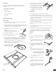
Attaching and securing the wiring to the speaker
CSP-162
1. Using a slotted screwdriver, remove the horizontal
screw of the strain-relief fitting closest to the
cover plate door.
2. Loosen the hold-down screws of the sliding
pieces of the strain-relief fitting with a Phillips
head screwdriver.
3. Run the wires through the opening
of the fitting and plug the removable
locking connector into the connector
socket in the speaker.
Warning: DO NOT FORCE THE
CONNECTOR INTO THE SOCKET.
4. Replace the horizontal screw that
was removed.
5. Tighten the strain relief fitting by
gradually tightening both of the
horizontal screws.
6. Once the speaker cable is securely
clamped into place, tighten the two
hold-down screws.
Caution: If using plenum cable, do not
over tighten the strain relief fitting. It
can strip the cable and cause damage.
7. Once the wires have been installed
and are securely clamped, close the
cover plate door and secure it by
tightening the screw with a Phillips
head screwdriver.
CSP-142
1. Plug the removable locking connector with the connected
speaker wires into the connector socket in the speaker.
Warning: DO NOT FORCE THE CONNECTOR INTO THE SOCKET.
2. Replace the cover by replacing the two screws attaching it to the
backcan.
Important: Make sure all wiring conforms to local building codes.
1 2 3 4
INLOOP
THRU
LOOP
THRU
IN
+ + – –
1 2 3 4
FROM AMPLIFIER OR
PREVIOUS SPEAKER
–
+
TO NEXT
SPEAKER
–
+
1 2 3 4
FROM AMPLIFIER OR
PREVIOUS SPEAKER
–
+
TO NEXT
SPEAKER
–
+
AMPLIFIER–+
1 2 3 4
1 2 3 41 2 3 4
+
–
TO SUBSEQUENT SPEAKERS
100 V
7.5
15
30
3.7
7.5
15
30
70 V
16R
16R
100 V
15
30
60
7.5
15
30
60
70 V
16R
16R
1 2 3 4
INLOOP
THRU
LOOP
THRU
IN
+ + – –
1 2 3 4
FROM AMPLIFIER OR
PREVIOUS SPEAKER
–
+
TO NEXT
SPEAKER
–
+
1 2 3 4
FROM AMPLIFIER OR
PREVIOUS SPEAKER
–
+
TO NEXT
SPEAKER
–
+
AMPLIFIER–+
1 2 3 4
1 2 3 41 2 3 4
+
–
TO SUBSEQUENT SPEAKERS
100 V
7.5
15
30
3.7
7.5
15
30
70 V
16R
16R
100 V
15
30
60
7.5
15
30
60
70 V
16R
16R
▪ ▪ ▪ ▪ ▪ ▪ ▪ ▪ ▪ ▪ ▪ ▪ ▪ ▪ ▪ ▪ ▪ ▪ ▪ ▪ ▪ ▪ ▪ ▪ ▪ ▪ ▪ ▪ ▪ ▪ ▪ ▪ ▪ ▪ ▪ ▪ ▪ ▪ ▪ ▪ ▪ ▪ ▪ ▪ ▪ ▪ ▪ ▪ ▪ ▪ ▪ ▪ ▪ ▪ ▪ ▪ ▪ ▪ ▪ ▪ ▪ ▪ ▪ ▪ ▪ ▪ ▪ ▪ ▪ ▪ ▪ ▪ ▪ ▪ ▪ ▪ ▪ ▪ ▪ ▪ ▪ ▪ ▪ ▪ ▪ ▪ ▪ ▪ ▪ ▪ ▪ ▪ ▪ ▪ ▪ ▪ ▪ ▪ ▪ ▪ ▪ ▪ ▪ ▪ ▪ ▪ ▪ ▪ ▪ ▪ ▪ ▪ ▪ ▪ ▪ ▪ ▪ ▪ ▪ ▪ ▪ ▪ ▪ ▪ ▪ ▪ ▪ ▪ ▪ ▪ ▪ ▪ ▪ ▪ ▪ ▪ ▪ ▪ ▪ ▪ ▪ ▪
Setting Up