Wireless Outdoor Bridge User Guide Before operating the unit, please read this manual and retain it for future use 1
FCC Interference Statement This equipment has been tested and found to comply with the limits for a Class B digital device pursuant to Part 15 of the FCC Rules. These limits are designed to provide reasonable protection against radio interference in a commercial environment. This equipment can generate, use and radiate radio frequency energy and, if not installed and used in accordance with the instructions in this manual, may cause harmful interference to radio communications.
Contents Chapter 1 Introduction..................................................................................................4 1.1 Features and Benefits......................................................................................4 1.2 Packing List.....................................................................................................5 Chapter 2 Hardware Installation...................................................................................6 2.1 Panel Layout ................
Chapter 1 Introduction Thank you for choosing the outstanding wireless bridge for wireless point-to-point bridging applications. This wireless bridge offers a low-cost alternative to installing cable or dedicated telephone lines. You can connect two or more buildings quickly and easily with no expensive, time-consuming cable installation and no monthly service fees (unlike leased 56K, ISDN or T1 lines).
1.2 Packing List 1. 2. 3. 4. 5. 6. 7. 8. 9. 10. 11. 12.
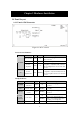
Chapter 2 Hardware Installation 2.1 Panel Layout 2.1.1 Panel of DC-Converter Figure 2-1 DC-Converter DC-Converter Indicator: Function LED Color Status DC-Converter Green Bridge Green On Power has being applied to DC-Converter. On Power has being sent from DC OUT. On Power has being applied to Power Amplifier. Only functionally when the Power Amplifier has been set into this device. Blinking Data has been sent via Power Amplifier.
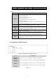
LED Function Color Status Description on the corresponding LAN port. Table 2-2 Port: Port RESET To Bridge With Power Amplifier Only DC OUT LAN1 (PoE) LAN2 Description To reset system settings to factory defaults, please follow the steps: 1. Power off the device, 2. Press the reset button and hold, 3. Power on the device, 4. Keep the button pressed about 5 seconds, 5. Release the button, 6. Watch the M1 LED, it will flash 8 times and then M1 flash once per second.
2.1.3 Side Panel of Bridge Figure 2-3 Side Panel of Bridge Port LAN1 Description DC connector comes with 12 voltage power which connects with DC-out in the DC-Converter. Connects to the LAN1 port which locates in the side panel of DC-converter. LAN2 Connects to the LAN2 port which locates in the side panel of side panel of DC-converter. DC IN Table 2-5 2.1.
2.2 Procedure of Hardware Installation Figure 2-6 1. Decide how to place Bridge Because this product is a radio device works in the 2.4 GHz frequency range. For optimum utilization, installing this product away from microwave ovens or other devices, operating in the 2.4 GHz frequency range, which can cause signal interference.
prevent an electrical surge from traveling through the antenna cable and into the building. Lightning protection for a building is more forgiving than protection of electrical devices. A building can withstand up to 100,000 volts, but electrical equipment may be damaged by just a few volts. Direct earth grounding of the antenna and the Lightning Protector is necessary to protect the installation from lightning and the build- up of static electricity.
Figure 2-7 Lightning Protector 6. Connect the Ethernet and Power Cable Ÿ Connect the power code to the DC-IN port on the rear panel of the DC-Injector. Ÿ Connect an Ethernet cable to the RJ-45 port (To LAN) on the rear panel of the DC-Injector. Use the straight cable to connect to the HUB/SWITCHA or use the crossed cable to connect to the PC’s Network Interface Card (NIC).
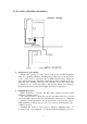
7. The Internal Connection of Bridge a. Without Power Amplifier Figure 2-8 Internal Construction without Power Amplifier Ÿ Connect DC-OUT of the DC-Converter to DC-IN which locates in the side panel of the Bridge Module Board with a Power Cable (320mm). Ÿ Connect DC-Converter and Bridge Module Board on each LAN1 port with a RJ-45 Cable. Ÿ Connect the N-Type(Fu) to SMA(Mu) Cable to the SMA port (Fu) which locates in the side panel of the Bridge Module Board.
b. With Power Amplifier Inside Figure 2-9 Internal Construction with Power Amplifier Ÿ Connect the SMA port (Fu) of the DC-Converter (To Power Amplifier) to the SMA port (Fu) of the Power Amplifier (IN) with a longer SMA (Mu) to SMA (Mu) Cable (330mm). Ÿ Connect the SMA port (Fu) of the Bridge Module Board (Under the Power Amplifier) to DC-Converter (To Bridge) with a shorter SMA (Mu) to SMA (Mu) Cable (100mm). Ÿ Connect DC-Converter and Bridge Module Board on each LAN1 port with a RJ-45 Cable.
Without Additional DC-Injector Figure 2-11 14
8. Installing the Outdoor Bridge a. Mounting Bracket on the wall Figure 2-13 b. Mounting Bracket on the Mast with the U-blots The mast must (not provided) be constructed of sturdy, weatherproof, no corrosive material such as galvanized or stainless steel construction pipe.
9. Connect to the other Bridge For some special reasons, you may need to install two bridges as a wireless repeater to lengthen the coverage range. Connect two bridges using a crossed cable and plug into the LAN2 port in the side panel of the DC-Converter as shown in Figure 2-2. Refer to the Chapter 3.3 for creating two of Bridges as a wireless repeater. 10. Antenna Alignment In case Bridge A is connecting with network IP 192.168.123.100. Bridge B is connecting with network IP 192.168.123.101. 1.
Chapter 3 Create a Bridge Network Environment 3.1 Bridge Configuration 1. 2. 3. 4. Login this device with the administrator’s password as “admin” (default). Select Primary Setup. In the Primary Setup page, make sure the Mode is Bridge. Enter the address into IP Address field which is in the same subnet with your network environment. 5. Set the “Channel” and “SSID ” of this device and another one which you want to connect in the same channel and SSID. 6. Save the settings above and then reboot this device.
1. Multipath propagation Transmitted signals can combine with reflected ones to corrupt the signal detected by the receiver. The PATH between two antennas is a straight line as shown in Figure 3-2. Any obstacle in this PATH can redirect parts of the transmitted signal as shown in Figure 3-3. The best propagation path is a clear line of sight with good clearance between the PATH and any physical obstacle.
2. Path loss Path loss between the transmitter and receiver is a key consideration when designing a wireless LAN solution. Expected levels of path loss, based on the range between the transmitter and receiver, provide valuable information when determining requirements for transmit power levels, receiver sensitivity and signal-to-noise ratio. Actual path loss depends on the transmit frequency, and it grows exponent ially as the distance increases between the transmitter and receiver.
3. Physical environment and Obstructions Open areas provide better coverage range than closed areas. Also, the obstructer such as steel buildings or trees can block or decrease communication between bridges. To avoid this situation, the antennas should be located in where is no or few obstruction between the sending and receiving antennas. 4.
3.3 Connect Buildings by using Bridges Wireless point-to-point networks use technologies very similar to wireless LANs. A radio-based wireless point-to-point network as shown in Figure 3-7 and Figure 3-8 is currently the most common method for providing connectivity within a metropolitan area. All of these bridges have to use highly directional antennas to focus the signal power in a narrow beam, in order to maximizing the transmission distance.
Figure 3-8 22
3.3.2 Repeater Configuration The repeater configuration extends maximum communication range beyond the radio horizon. An additional pair of bridges is set up at an intermediate site, one oriented towards each of the end points. Transmissions from one end point are received by the intermediate bridge facing it, passed by wire to the other intermediate bridge, and retransmitted to the other end point. This configuration normally requires directional antennas for maximum range.
Chapter 4 General Configuration 4.1 Log in and Start up This product provides a web based configuration scheme, make possible to configure by web browser such as Netscape Communicator or Internet Explorer. 1. Start the web browser, and disable the proxy or add the IP address of this product into the exceptions of Proxy setting. Then, type this product’ s IP address (the default setting is 192.168.123.254) in the Location (for Netscape) or Address (for IE) field and press ENTER. 2.
Figure 4.1 When this device is printing, there may appear a “Kill Job” button on the Sidenote column. You can click this button to cancel the current printing job manually. 4.3 Tool Box This option enables you to change the administrator password. There are some useful buttons in this page: Item Function View Log View the system logs Reboot Reboot this device Backup Setting You can backup your settings by clicking this button and save it as a bin file.
NOTE: we strongly recommend you to change the system password for security reason. Figure 4.2 4.4 Primary Setup Figure 4.3 This option is primary to enable this product to work properly. 1.IP Address: the IP address of this device. 2.Mode: the operating mode of this device.
is the normal operation mode of a Bridge. Users can change it to the “AP” mode if you want this product to work as a wireless access point. Figure 4.4 3.Network ID (SSID): Network ID is used for identifying the Wireless LAN (WLAN). Client stations can roam freely over this product and other Access Points that have the same Network ID. (The factory setting is “default”). Note: This item won’t take effect in “Bridge ” mode. 4.Channel: The radio channel number.
Figure 4.5 MAC Address Control allows only client devices with specified MAC addresses to associate and pass data through this device. Item Function MAC Address Control Check “Enable” to enable the “MAC Address Control”. All of the settings in this page will take effect only when “Enable ” is checked. Connection control Check "Connection control" to enable the controlling of which wired and wireless clients can connect to this device.
Association control Check "Association control" to enable the controlling of which wireless client can associate to the wireless LAN. If a client is denied to associate to the wireless LAN, it means the client can't send or receive any data via this device. Choose "allow" or "deny" to allow or deny the clients, whose MAC addresses are not in the "Control table", to associate to the wireless LAN. Control table "Control table" is the table at the bottom of the "MAC Address Control" page.
Select a specific client in the “DHCP clients” Combobox, and then click on the “Copy to” button to copy the MAC address of the client you select to the ID selected in the “ID” Combobox. Previous page and Next Page To make this setup page simple and clear, we have divided the “Control table” into several pages. You can use these buttons to navigate to different pages.
Chapter 5 System Troubleshooting Problem and Indication Possible Solution/ Answer What is this bridge’ s default IP Address? This bridge’ s default IP address is 192.168.123.254 I reset this bridge to factory defaults but the IP address hasn't changed. Resetting this device to factory defaults does not reset the device's IP address to 192.168.123.254 I can't exchange data over a Point to- Point link. Check the following steps: 1. Ensure that each device has the same Channel and SSID. 2.
Problem and Indication Possible Solution/ Answer but there is no Ethernet activity. this is not the case, the port is inactive. Try another port on the hub or another UTP cable. 2. Ensure that Ethernet port in unit is working. Ping this device to confirm Ethernet connection. 3. Verify that you are using a cross-over UTP cable (pins 1 & 3, 2 & 6) if connected directly to workstation, or a straight-through cable if connected to a hub.
Appendix A TCP/IP Configuration for Windows 95/98/ME/2000/XP This chapter will introduce how to install the TCP/IP protocol in the personal computer and using the TCP/IP setting to connect this device correctly. A.1 Configure Windows 95/98/ME Platforms for working with this device 1. Connect this device to a computer by general network cable. 2. On the Windows 95/98/ME Platforms, click Start button and choose Settings, then click Control Panel . 3.
5. Double click Protocol to add TCP/IP protocol. 6. Select Microsoft item in the manufactures list. Then choose TCP/IP in the Network Protocols list. Click OK button to return to Network window. 7. The TCP/IP protocol shall be listed in the Network window. Click OK to complete the install procedure and restart your PC to enable the TCP/IP protocol. 8. After rebooting, click Start button and choose Settings, then click Control Panel. 9. Double click Network icon.
11. Select Specify an IP address in the IP Address tab. The default IP address of this product is 192.168.123.254. So please use 192.168.123.xxx (xxx is between 1 and 253) for IP Address field and 255.255.255.0 for Subnet Mask field.
12. In the Gateway and DNS tab, do not put anything. 13. Click OK button to finish the TCP/IP setting and restart the computer.
A.2 Configure Windows 2000/XP Platforms for working with this device 1. After complete installation the windows 2000/XP, the system will automatically install the TCP/IP protocol. 2. Connect this device to a computer by general network cable. 3. On the Windows 2000/XP platform, right click My Network Places on the desktop then select Properties. 4. In the Network Connections dialogue window, right click the network connection icon of Wireless LAN PC Card and select properties.
5. In the General tab, choose Internet Protocol (TCP/IP) and click the properties button. 6. In the General tab, select Use the following IP address and set a IP address which is in the same sub net with this product(default is 192.168.123.254). 7. Do not put anything in the Default gateway and DNS field. Click the OK button to complete TCP/IP setting.
Appendix B Technical Specifications General Data Transfer Rate 11, 5.5, 2 and 1 Mbps, Auto Fall- Back Range (open environment) 11 Mbps –300m/450m ( 23 dBm output power) 5.
Radio RF Output Power 29.5dBm(891mW)--FCC 20dBm(100mW)--CE Environment Temperature Range Humidity (non-condens ing) 0 to 50° C (32 to 131 °F)-operating -20 to 80 ° C(-4 to 176 °F) storage 5%∼95% typical Physical Specifications Dimensions 354(L)mm * 249(W)mm * 89(H)mm 13.9(L)in. * 9.8(L) in. * 3.5(H) in. Weight 2.1Kg Electrical Power Supply Surge Arrester Active Ethernet (power over Ethernet) –48 VDC/0.