
User's Manual


7
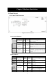
LED Function Color
Status Description
on the corresponding LAN port.
Table 2-2
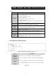
Port:
Port Description
RESET
To reset system settings to factory defaults, please follow the steps:
1. Power off the device,
2. Press the reset button and hold,
3. Power on the device,
4. Keep the button pressed about 5 seconds,
5. Release the button,
6. Watch the M1 LED, it will flash 8 times and then M1 flash once per
second.
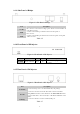
To Bridge
Two ports (LAN1and LAN2) connect with the bridge module board.
Refer to the 2.1.3 Side Panel of Bridge for more detail.
With Power
Amplifier
Only
This item include two sub-items (To Power Amplifier and To Bridge)
only use in when the power amplifier has been used. Refer to the 2.1.2
Side Panel of DC-Converter for more detail.
DC OUT
DC connector transmits 12 voltage power which connects with DC-IN
in the side panel of bridge.
LAN1 (PoE)
LAN port connects to the DC-Injector which uses PoE (Power over
Ethernet) technology. This port has the physical connection to the
LAN1 port which locates in the side panel of DC-Converter.
LAN2
LAN port uses to connect to the other bridge has the physical
connection to the LAN2 port which locates in the side panel of
DC-Converter.
Table 2-3
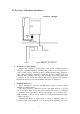
2.1.2 Side Panel of DC-Converter
Figure 2-2 Side Panel of DC-Converter
Port Description
To Power
Amplifier
Connects to the power amplifier use the SMA to SMA cable.
To Bridge
Connects to the Bridge’s module board use the SMA to SMA cable.
LAN1
Connects to the LAN1 port which locates in the side panel of bridge.
LAN2
Connects to the LAN2 port which locates in the side panel of bridge.
Table 2-4