Wireless LAN Card User Guide Before operating the unit, please read this manual and retain it for future Long Range Wireless LAN Card The user guide is fit for both Wireless LAN Card and Long Range Wireless LAN Card
Contents 1. Introduction 1 1.1 Package Contents 1 1.2 PC Card Description 1 1.3 System Requirements 2 1.4 Features and Benefits 2 1.5 Applications 2 1.6 Network Configurations 3 2. Installing Driver and Utility 8 2.1 Installation for Windows 98/ME/2000/XP 8 2.2 Checking after Installation 15 2.3 Wireless LAN Client Utility 17 2.4 Uninstalling Driver and Utility 30 3. Connecting to a Network 31 3.1 Checking and Adding Client for Microsoft Networks 31 3.
Chapter 1 Introduction This chapter describes the package contents, PC Card description, system requirements, features & benefits, applications and network configurations of our wireless LAN products. 1-1 Package Contents The PC Card package contains the following items as shown in Figure 1-1 1. One PC Card 2. One Installation CD 3. One Quick Installation Guide Wireless LAN PC Card Installation CD Wirel ess LAN PC Card Quick I nstallation Guid e IE E E 8 02 .
1- 3 System Requirements Installation of the PC Card requires: 1. PC/AT compatible computer with PCMCIA Type II slot. 2. Windows 98//ME/2000/XP operating system environment. 3. Minimum 1.3M bytes free disk space for installing the PC Card driver and utility program. 1- 4 Features and Benefits 11Mbps data transfer rate High-speed data transmission High transmit output power Long operating range, up to three times (Long Range PC Card Only) range of standard products IEEE 802.
There are many situations where wires cannot or not easily be laid. Historic buildings, older buildings, open areas and across busy streets make the installation of LANs either impossible or very expensive. 2. Temporary workgroups Consider situations in parks, athletic arenas, exhibitions, disaster-recovery, temporary office and construction sites where one wants a temporary WLAN established and removed. 3.
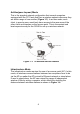
Ad-Hoc(peer-to-peer) Mode This is the simplest network configuration that several computers equipped with the PC Cards that form a wireless network whenever they are within range of one another (Figure 1-3). In ad-hoc mode, each client, is peer-to-peer, would only have access to the resources of the other client and requires no the access point. This is the easiest and least expensive way for the SOHO to set up a wireless network.
Figure 1-4 Infrastructure Mode Extended-range independent WLAN using AP as repeater If wired to an Ethernet network as shown in Figure 1-5, the AP serves as a bridge and provides the link between the server and the wireless clients. The wireless clients can move freely throughout the coverage area of the AP while remaining connected to the server. Since the AP is connected to the wired network, each client would have access to server resources as well as to other clients.
Access points have a finite range, on the order of 50 meters indoor and 100 meters outdoors. In a very large facility such as an enterprise, a warehouse, or on a college campus, it will probably be necessary to install more than one access point to cover an entire building or campus, as shown in Figure 1-6. In this scenario, access points hand the client off from one to another in a way that is invisible to the client, ensuring the connectivity.
Figure 1-7 Wireless router and IP Sharing 7
Chapter 2 Installing Drivers&Client Utility This chapter describes how to install the PC Card drivers and client utility under Windows 98/ME/2000/XP. 2- 1 Installation for Windows 98/ME/2000/XP During the installation, Windows 98/ME/2000/XP may need to copy Windows systems files from the Windows 98/ME/2000/XP installation diskette or CD-ROM. Therefore you will need a copy of the Windows 98/ME/2000/XP installation diskette or CD-ROM at hand before installing the driver.
Figure 2-1-1 8. Make sure that the network protocol parameters are set correctly for your computer. These include the IP address, Subnet mask, Gateway and DNS. If you are unfamiliar with how to set network protocol parameters, refer to Chapter 3 Connection to Network for details.
~ Install Wireless PC Card Driver 1. Turn on the computer. 2. Right-click on My Computer icon on the Windows desktop to chose Properties and then System Properties window will pop out. 3. Click on the tab Device Manager and then move the mouse to Network Adapters node to expend the tree list by clicking on the plus sign. 4. Remove Wireless LAN PC Card that you have installed already. 5. Uninstall the old driver. 6. You must remove the old existing driver before installing the new driver. 7.
c. Figure 2-1-2 Click Update Driver button from the Driver tab as shown in Figure 2-1-3.
d. Click next of the Welcome to Upgrade the Device Driver Wizard dialog box. The Install Hardware Device Driver dialog window will be showed up as shown in Figure 2-1-4. Figure 2-1-4 e. Choose Display a list of the known drivers for this device so that I can choose the specific driver and click Next as shown in Figure 2-1-5.
f. In the Network Type dialog window, choose Network adapters and then click Next as shown in Figure 2-1-6. Figure 2-1-6 g. Select the network adapter for 802.11b Wireless LAN PC Card and then click Next. The Start Device Driver Installation dialog window will show up, click Next to enter the Digital Signature Notice window as shown in Figure 2-1-7.
h. Click Yes to continue the installation procedure as shown in Figure 2-1-8. Figure 2-1-8 i. Click Finish to complete the installation procedure as shown in Figure 2-1-9.
2- 2 Checking after Installation After installing the driver and utility, follow the steps below to check that the PC Card is operating correctly. 1. Click the Start button, select Settings, and then click Control Panel. 2. In the Control Panel window, double-click the System icon, and then select the Device Manager tab. 3. Double-click Network adapters, then select Wireless LAN PC CARD as shown in Figure 2-2-1. Figure 2-2-1 4. Click the Properties button, and then check the message.
Figure 2-2-2 5. If you find the Yellow (?) sign on the adapter or the above message is not displayed, it shows the installation is not successful or the wireless LAN PC Card is not operating properly. Uninstall and re-install the driver, referring to Chapter 2-6 Uninstalling Driver and Utility.
2- 3 Wireless LAN Client Utility Wireless LAN Client Utility is used to display or change the PC Card information about link, configuration, encryption, and utility/driver/firmware version information. The client utility will also help you with site selection. The client utility will be installed automatically after installing the driver and utility. The PC Card Utility icon will appear in the System Tray in the bottom right corner on your screen as shown in the Figure 2-3-1 and Table 2-3-1.
Figure 2-3-2 1. Menu of System Icon Right-click on the system tray icon, the icon menu will display as shown in Figure 2-3-3. Below is the introduction to this icon menu.
Wireless Radio On/ Wireless Radio Off The first two items in the icon menu are used to turn on/off the wireless radio. When the wireless radio is turned off, a red cross is placed on the system tray icon as shown in Figure 2-3-4. When the wireless radio is turned on, the icon will vary in colors depending on the link quality as described in the Table 2-3-1. z Figure 2-3-4 Remove Status Icon This item allows you to set the System Tray Icon to appear or disappear.
Wireless Network Status This item launches the PC Card Utility with the tab Status that displays the information about link status to users. z Advanced Configuration This item launches the PC Card Utility with the tab Configuration that allows users to configure PC Cards to suit their specific network settings. z WEP Encryption This item launches the PC Card Utility with the tab WEP Encryption that allows users to set up the Encryption Key which is used in their network environment.
2. Status Shows status information about the radio link, as shown in Figure 2-3-6. Figure 2-3-6 Associated BSSID – means the wireless client is connected to an access point. BSSID is shown in the form of six hex digits which is the MAC address of the access point. z Scanning – means the wireless client is searching for an available access point in infrastructure mode.
Throughput (Bytes/sec) z Tx: shows the outgoing (sent) data speed. z Rx: shows the incoming (received) data speed. Link Quality In infrastructure mode, this bar displays the transmission quality between a WLAN station (Access Point) and Wireless LAN PC Card. In Peer-to-Peer mode (Ad-Hoc), this bar displays the link quality between two Wireless LAN PC Cards. Signal Strength This bar displays the signal strength level. The higher bar is, the more powerful radio signal is received by the PC Card.
Profile You can give a name for this field to a setting of configuration parameters, such as Network Name, Network Type, Transmit Rate, Encryption (WEP Security), etc. It makes much easier for users to change WLAN configuration settings who need to switch working places frequently. Suppose that a user has to work between the two different offices where there are different network settings.
Peer to Peer: If two or more stations exchange data directly without an access point, you need to select Peer-to-Peer mode. Each station in a Peer-to-Peer (Ad-Hoc) network must specify the same network name (SSID) and peer-to-peer channel. z Access Point: If at least one access point involves in the communications in a group of stations, you need to select Infrastructure mode. Each station needs to specify the same network name (SSID) as the access point.
Figure 2-3-9 Transmit Rate The transmission rate on which the data packets are transmitted by the client can be specified in this drop-down list as shown in Figure 2-3-10. Below are the available transmission rates. Full Automatic PC Card chooses the highest available transmission rate 11 Mbps Allows only 11 Mbps operation 5.5 Mbps Allows only 5.
Figure 2-3-10 Defaults Once this button is pressed, all the settings will be set back to the default settings. 4. Encryption Encryption is designed to make the data transmission more secure. you can select 64 or 128-bit WEP (Wired Equivalent Privacy) key to encrypt data (Default setting is Disable) as shown in Figure 2-3-11. WEP encrypts each frame transmitted from the radio using one of the Keys from this panel.
Use WEP Key This drop-down list allows you to specify which of the four encryption keys that you want to use. z Create Keys with Passphrase Type a character string in the field Passphrase. z Disabled Select Disabled item in the Encryption(WEP security) drop-down list allows you to disable the encryption function.
5. Site Survey Browse the available access points in your network environment by clicking the Rescan button and make a connection to one of them by pushing the Connect button in the Site Survey tab as shown in Figure 2-3-12.
6. About About tab shows the product/driver/utility/PC Card firmware version as shown in Figure 2-3-13. Users have to use this version number when reporting their problems to technical support.
2- 4 Uninstalling Driver and Utility If the PC Card installation is unsuccessful for any reason, the best way to solve the problem may be to completely uninstall the PC Card and its software and repeat the installation procedure again. 1. Insert the Wireless LAN PC Card into the PCMCIA slot. 2. Right click My Computer--->Select Properties. 3. On the Hardware tab, choose Device Manager, and click Network .Adapter. 4. Choose Wireless LAN PC Card and remove it. 5.
Chapter 3 Connecting to a Network This chapter describes how to prepare for connection to network after install the PC Card drivers and utility. The following is required for all computers if you want to connect to a network. 1. 2. 3. 4. 5. Check Client for Microsoft Networks is installed. Check NetBEUI -> Wireless LAN PC Card installed. Check TCP/IP -> Wireless LAN PC Card is installed. Check file and printer sharing for Microsoft Networks. Check computer name and workgroup name.
Figure 3-1 5. Select Microsoft for Manufacturer and Client for Microsoft Networks for Network Client, and then click OK. 3-2 Checking and Adding NetBEUI NetBEUI is a protocol you can use to connect to Windows NT, Windows for Workgroups, or LAN Manager servers. If you work on Microsoft network environment, you need to set up NetBEUI protocol. 1. Repeat the step 2 and 3 of Chapter 3-1 Checking and Adding Client for Microsoft Networks. 2.
3-3 Checking and Adding TCP/IP TCP/IP is the protocol you use to connect to the Internet and wide-area networks. If you want to connect to Internet, you need to set up TCP/IP protocol. 1. Repeat the step 2 and 3 of Chapter 3-1 Checking and Adding Client for Microsoft Networks. 2. Select Configuration tab to check TCP/IP -> Wireless LAN PC Card is installed. If no, click the Add button. Select Protocol and click the Add button. 3.
3-4 Checking and Adding File and Printer Sharing for Microsoft Networks File and printer sharing for Microsoft networks gives you the ability to share your files or printers with Windows NT and Windows for Workgroups computers. If you want to share your files or printers with Microsoft networks, you need to set up this service. 1. Repeat the step 2 and 3 of Chapter 3-1 Checking and Adding Client for Microsoft Networks. 2.
Chapter 4 Troubleshooting This chapter describes the problems and corresponding solutions that may occur when installing a PC Card. Symptom Windows does not detect the PC Card when installed. Driver fails to load Solution Verify that the PC Card is properly inserted into the PC Card slot. Check whether the computer has a Plug and Play BIOS. Windows 98/ME/2000/XP might not detect the PC Card if a previous installation of the PC Card was cancelled before it was finished.
Verify that the SSID of the PC Card matches that of the access point. Use No resource conflicts were the Network Configuration Properties detected, but the wireless Application in the Control Panel to station does not attach to the modify the SSID. Verify that the Network Mode of the network PC Card is configured correctly. Nonfunctioning card LED Weak signal or intermittent connection. The PC Card is not powered on. The cause may be: y No Driver loaded or installed.
Appendix A Product Specifications General Radio Data Rate 11, 5.5, 2 and 1 Mbps, Auto Fall-Back 11 Mbps – 150m 450m(Long Range PC Card ) 5.5 Mbps –200m Range (open environment) 600m(Long Range PC Card) 2 Mbps – 250m 750m(Long Range PC Card) 1 Mbps – 400m 1200m(Long Range PC Card) Operating Voltage 3.3V/5V Regulation Certifications FCC Part 15/UL, ETSI 300/328/CE Compatibility LED Indicator Fully interoperable with IEEE802.
Radio Frequency Band 2.4 – 2.484 GHz Radio Type Direct Sequence Spread Spectrum (DSSS) Modulation CCK (11, 5.5Mbps) DQPSK (2Mbps) DBPSK (1Mbps) Operation Channels 11 for North America, 14 for Japan, 13 for Europe, 2 for Spain, 4 for France RF Output Power 15 dBm 20 dBm (Long Range PC Card for CE) 23 dBm (Long Range PC Card for FCC) Antenna Two jacks for external antenna Sensitivity @FER=0.08 11 Mbps < -85dBm <-87dbm( Long range PC Card) 5.
Physical Specifications Form Factor PCMCIA Type II PC Card Dimensions 118(L) mm x 54(W) mm x 7.
Federal Communication Commission Interference Statement This equipment has been tested and found to comply with the limits for a Class B digital device, pursuant to Part 15 of the FCC Rules. These limits are designed to provide reasonable protection against harmful interference in a residential installation. This equipment generates, uses and can radiate radio frequency energy and, if not installed and used in accordance with the instructions, may cause harmful interference to radio communications.
This device is intended only for OEM integrators under the following conditions: 1) The antenna must be installed such that 20 cm is maintained between the antenna and users, and 2) The transmitter module may not be co-located with any other transmitter or antenna. As long as 2 conditions above are met, further transmitter test will not be required.