
User's Manual


© 2014 Araknis Networks
®
8
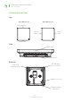
Araknis Networks Wireless Access Point
Quick Start Guide
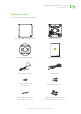
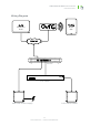
Step 2. Install Wiring
Decide how the WAP will be powered, then install the required wiring.
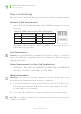
Network Cable Requirements
• Use a Cat5e/6 straight-through cable. 568B termination is recom-
mended:
EIA/TIA 568B Pattern (Gold Pins Facing Up)
Pin 1 White/Orange Pin 5 White/Blue
Pin 2 Orange Pin 6 Green
Pin 3 White/Green Pin 7 White/Brown
Pin 4 Blue Pin 8 Brown
• Maximum cable length is 328 feet (100m). A repeater device is
required for longer runs.
PoE Requirements
Caution – Use an 802.3af/at compliant PoE injector, switch, or router to
power the WAP. Non-compliant devices can harm the WAP and lead to
unpredicted results.
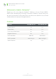
Power Requirements for Non-PoE Applications
• AC Outlet – 100-240V AC, 50/60Hz (AN-100: 0.3A; AN-300: 0.6A)
• DC Input – 12V DC 1A (AN-100); 2A (AN-300)
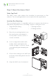
Wiring Instructions
Warning – Do not connect any equipment to the wiring until every-
thing has been terminated and testing is complete.
A. For PoE installations, run a network cable from the PoE device to
the WAP and terminate both ends to the same pattern. The DC
power supply is not needed.
B. For non-PoE installations, locate an outlet for the power supply.
Pro Tip – If needed, extend a 2-conductor power wire from the power
supply to the WAP.