
User's Manual
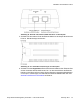
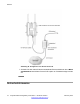
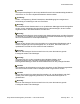
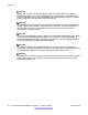
Table Of Contents
- Contents
- Chapter 1: Regulatory Compliance Statements
- Federal Communications Commission (FCC) Compliance Notices
- Class B Interference Statement
- FCC Caution
- RF Radiation Exposure and Hazard Statement
- Non-Modification Statement
- Deployment Statement
- Outdoor operating restrictions
- Dynamic Frequency Selection (DFS) in the 5.0 GHz UNII bands
- Canadian IC Statements
- European Union and European Free Trade Association (EFTA) Regulatory Compliance
- Declaration of Conformity
- European Community Declaration of Conformity
- Countries of Operation and Restrictions of Use in the European Community
- Operation Using the 2.400 to 2.4835 GHz Channels in the European Community
- Operation Using the 5.15 to 5.25 GHz, 5.25 to 5.35 GHz, and 5.470 to 5.725 GHz Channels in the European Community
- Russia, Belarus, and Kazakhstan Requirement
- Antenna Statement
- Chapter 2: Devices with detachable antennas
- Chapter 3: English
- Kapitel 4: Deutsch
- Einführung
- Sicherheitsmaßnahmen
- Installation des WLAN-AP 8120-O
- Hardware
- Kabelanschlüsse
- Abdichten des Ethernet-UTP-Kabels
- Mounten eines WLAN-AP 8120-O an einem vertikalen Mast
- Mounten eines WLAN-AP 8120-O an einem horizontalen Mast
- Mounten eines WLAN-AP 8120-O an einer Wand
- Installation des Ethernet-Überspannungsableiters
- Installation des Power over Ethernet-Injektors
- Sicherheitshinweise
- Capítulo 5: Español
- Introducción
- Precauciones de seguridad
- Instalación del WLAN AP 8120-O
- Hardware
- Requisitos de cableado
- Impermeabilización del cable UTP Ethernet
- Instalación del WLAN AP 8120-O en un poste vertical
- Montaje del WLAN AP 8120-O en un poste horizontal
- Instalación del WLAN AP 8120-O en una pared
- Instalación del disipador de sobretensiones Ethernet
- Instalación del inyector Power over Ethernet
- Advertencias de seguridad
- Chapitre 6 : Français
- Capítulo 7: Português do Brasil

Abbildung 46: DATA IN- und DATA & POWER OUT-Ports am PoE-Injektor
5. Schließen Sie das andere Ende des Ethernet-Kabels an den Avaya WLAN-Access
Point an. Die AC-Anzeige leuchtet auf.
Abbildung 47: AC- und PORT-Leuchtanzeigen am PoE-Injektor
6. Schließen Sie das abgedichtete Ende des Ethernet-Kabels an den Ethernet-Port
auf der Unterseite des WLANAP 8120-O an. Vor dem
Anschließen des Ethernet-
Kabels an den Ethernet-Port müssen Sie den Stecker ordnungsgemäß abdichten
und crimpen. Anweisungen zum Abdichten des Ethernet-Kabels finden Sie unter
Abdichten des Ethernet-UTP-Kabels auf Seite 54.
Installation des WLAN-AP 8120-O
Avaya WLAN 8100 Regulatory Information — WLAN AP 8120-O February 2012 73