
User's Manual

~21~
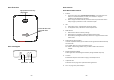
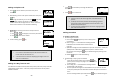
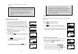
Base Illustration
Base unit Diagram
Page
(handset locator
only
)
/ Registration
Power LED: blue color
In use LED: white
color
Reset Button
DC Jack
Phone Jack
Line Jack
~22~
Base Features
Basic Base Station Features
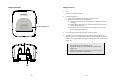
1. Antenna
a. The antenna port has a reversed thread connector; to remove antenna or
cable, turn counterclockwise; to install, turn clockwise. Improper
installation may damage the connector.
b. When using an outdoor antenna, locate the antenna (not the base station
itself) as high as possible for a clear transmission path.
2. LED
a. Power (blue color): indicates base station has power.
b. In-Use (white color): indicates an active telephone line.
3. RESET Button
a. Restores base station to factory settings
b. Reset button is intended to prevent accidental system reset.
c. All handsets (including administrator) need to be re-registered after a base
station reset.
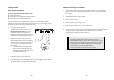
4. Page Button (Locate handset)
To find a misplaced handset; press “PAGE” and all registered handsets will beep
for 30 seconds.
Press “PAGE” again or any key on handset to stop.
Re: “PAGE” is for locating handset only, not able to make intercom with
handset.
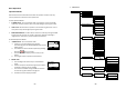
5. Registration Button (PAGE)
Enters registration mode along with handset, assigns handset ID (11-19).
6. Line Jack
Standard RJ-11C/CA-11A connector to plug in the telephone line
7. Telephone Jack
Another RJ-11C to plug in the optional answering machine
8. DC In: to plug in the power adaptor