1b/g Long Range Multi-Function AP EOA3630 User’s Manual Version : 1.
Table of Contents 11B/G LONG RANGE MULTI-FUNCTION AP ............................................................................................................................ 0 EOA3630 .................................................................................................................................................................................. 0 USER’S MANUAL..................................................................................................................................
4.3.6 WPA2 .............................................................................................................................................................. 26 4.3.7 WPA Mixed...................................................................................................................................................... 27 4.3.8 Radius Accounting........................................................................................................................................... 28 4.
1 Product Overview Thank you for using EOA3630. It is a powerful, enhanced, enterprise scale product with 7 multi-functions Access Point, Access Point with WDS function, Client Bridge, WDS Bridge, Repeater, AP Router and Client Router. EOA3630 is easily to install almost anywhere by wall mount kit and also support Power over Ethernet for quick installation. External N-type antenna provides better wireless signal quality and the antenna is upgradeable.
e) Wireless extensions to Ethernet networks Network managers in dynamic environments can minimize the overhead caused by moves, extensions to networks, and other changes with wireless LANs. f) Wired LAN backup Network managers implement wireless LANs to provide backup for mission-critical applications running on wired networks.
PPPoE/PPTP function support (AP Router/CR mode) SNMP Remote Configuration Management Easy to access internet via ISP service authentication Help administrators to remotely configure or manage the Access Point easily. QoS (WMM) support Enhance user performance and density High Speed Data Rate Up to 108Mbps Capable of handling heavy data payloads such as MPEG video streaming 1.3 Package Contents Open the package carefully, and make sure that none of the items listed below are missing.
1.4 System Requirement The following conditions are the minimum system requirement. A computer with an Ethernet interface and operating under Windows XP, Vista, 7 or Linux. Internet Browser that supports HTTP and JavaScript. 1.
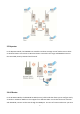
2 EOA3630 Multi-Function Instruction Guide 2.1 Access Point In the Access Point Mode with WDS Function, EOA3630 function likes a central connection for any stations or clients that support IEEE 802.11b/g and SuperG network. Stations and Client must configure the same SSID and Security Password to associate within the range. EOA3630 supports 4 different SSIDs to separate different clients at the same time. 2.
2.3 Client Bridge In the Client Bridge Mode, the EOA3630 function likes a wireless dongle. Connected to an Access Point wirelessly and surf internet whenever you want. Using Site Survey to scan all the Access Point within the range and configure its SSID and Security Password to associate with it. Connect you station to the LAN port of the EOA3630 via Ethernet. 2.
2.5 Repeater In the Repeater Mode, the EOA3630 can extend the wireless coverage area of another Access Point or Wireless Router. Access Point or Wireless Router must within the range and EOA3630 must use the same SSID, Security Password and Channel. 2.6 AP Router In the AP Router Mode, the EOA3630 has DHCP server build inside that allows you to configure easily via wireless. AP Router Mode can also support four different SSIDs.
within the range. 2.7 Client Router In the Client Router Mode, the EOA3630 has DHCP Server build inside that allows many LANs automatically generate an IP address to share the same Internet. Connect an AP/WISP Wirelessly and connect to LANs via wired. Client Router Mode is act completely opposite to the AP Router Mode.
3 Computer Configuration Instruction 3.1 Assign a Static IP In order to configure EOA3630, please follow the instruction below: 1. In the Control Panel, double click Network Connections and then double click on the connection of your Network Interface Card (NIC). You will then see the following screen. 2. Select Internet Protocol (TCP/IP) and then click on the Properties button. This will allow you to configure the TCP/IP settings of your PC/Notebook 3.
3.2 Logging Method After complete the IP settings from last section, you can now access the web-based configuration menu. 1. Open web browser 2. Enter IP 192.168.1.1 into you address filter. Auction: If you have changed the EOA3630 LAN IP address, make sure you enter the correct IP Address. 3. After connected to the EOA3630 successfully, browser will pop out a Windows Security window. Please enter the correct Username and Password. 4. The default Username and Password are both admin.
4 Wireless Configuration 4.1 Switching Operation Mode The EOA3630 supports 6 different operation modes: Access Point, Client Bridge, WDS Bridge, Repeater, AP Router, and Client Router. Click System Properties under System Section to begin. . Device Name: Specify a name for the device, but it is not the broadcast SSID. Country/Region: United States. Operation Mode: Select an operation mode via Radio Button. Click Apply to save the changed.
4.2 Wireless Settings 4.2.1 Access Point Mode Wireless Mode Select the desired 802.11 standard modes or SuperG mode. There are four different modes and they are 802.11b, 802.11g Only, 802.11 b/g mixed and SuperG. Channel / Frequency The channel availability is based on the country’s regulation. Auto Place a Check to enable Auto channel selection. AP Detection AP Detection can help to select a best channel by scan nearby area.
SSID Specify the SSID for current profile. VLAN ID Specify the VLAN tag for current profile. Suppressed SSID Place a Check to hide the SSID. Client will not be able to see the broadcast SSID in Site Survey. Station Separation Select the Radio Button to allow / deny client to communicate each other. Wireless Security Please refer to the Wireless Security section. Save / Cancel Press Save to save the changes or Cancel to return previous settings.
4.2.2 Client Bridge Mode Wireless Mode Select the desired 802.11 standard modes or SuperG mode. There are four different modes and they are 802.11b, 802.11g Only, 802.11 b/g mixed and SuperG. SSID Specify the SSID if known. SSID text box will be automatically fill in when select an AP in the Site Survey. Site Survey Using Site Survey to scan nearby APs and then select the AP to establish the connection. Prefer BSSID Specify the MAC address if known.
Refresh Press Refresh to scan again. Auction: If the Access Point is suppressed its own SSID, SSID section will be blank, the SSID must be filled in manually. 4.2.3 WDS Bridge Mode Wireless Mode Select the desired 802.11 standard modes or SuperG mode. There are four different modes and they are 802.11b, 802.11g Only, 802.11 b/g mixed and SuperG. Channel / Frequency The channel availability is based on the country’s regulation.
4.2.4 Repeater Mode Wireless Mode Select the desired 802.11 standard modes or SuperG mode. There are four different modes and they are 802.11g Only, 802.11 b/g mixed and SuperG. SSID Specify the SSID if known. SSID text box will be automatically fill in when select an AP in the Site Survey. Site Survey Using Site Survey to scan nearby APs and then select the AP to establish the connection. Prefer BSSID Specify the MAC address if known.
Refresh Press Refresh to scan again. Auction: If the Access Point is suppressed its own SSID, SSID section will be blank, the SSID must be filled in manually. 4.2.5 AP Router Mode Wireless Mode Select the desired 802.11 standard modes or SuperG mode. There are four different modes and they are 802.11b, 802.11g Only, 802.11 b/g mixed and SuperG. Channel / Frequency The channel availability is based on the country’s regulation. Auto Place a Check to enable Auto channel selection.
Auction: SuperG is a special feature in EOA3630. If the client does not support SuperG, it cannot establish a wireless connection successfully. SSID Specify the SSID for current profile. VLAN ID Specify the VLAN tag for current profile. Suppressed SSID Place a Check to hide the SSID. Client will not be able to see the broadcast SSID in Site Survey. Station Separation Select the Radio Button to allow / deny client to communicate each other.
4.2.6 Client Router Mode Wireless Mode Select the desired 802.11 standard modes or SuperG mode. There are four different modes and they are 802.11b, 802.11g Only, 802.11 b/g mixed and SuperG. SSID Specify the SSID if known. SSID text box will be automatically fill in when select an AP in the Site Survey. Site Survey Using Site Survey to scan nearby APs and then select the AP to establish the connection. Prefer BSSID Specify the MAC address if known.
Refresh Press Refresh to scan again. Auction: If the Access Point is suppressed its own SSID, SSID section will be blank, the SSID must be filled in manually. 4.3 Wireless Security Settings Wireless Security Settings section will guide you to the entire Security modes configuration: WEP, WPA-PSK, WPA2-PSK, WPA-PSK Mixed, WPA, WPA2, and WPA Mixed. We strongly recommend that uses WPA2-PSK as your security settings. 4.3.1 WEP Security Mode Select WEP from the drop down list to begin the configuration.
4.3.2 WPA-PSK Security Mode Select WPA-PSK from the drop down list to begin the configuration. Encryption Select Auto, TKIP or AES for Encryption type. Passphrase Specify the security password. Group Key Update Interval Specify Group Key Update Interval time. Group Key Update Timeout Specify Group Key Update Timeout time. Pairwise Key Update Interval Specify Pairwise Key Update Timeout time. 4.3.3 WPA2-PSK Security Mode Select WPA2-PSK from the drop down list to begin the configuration.
Passphrase Specify the security password. Group Key Update Interval Specify Group Key Update Interval time. Group Key Update Timeout Specify Group Key Update Timeout time. Pairwise Key Update Interval Specify Pairwise Key Update Timeout time. 4.3.4 WPA-PSK Mixed Security Mode Select WPA-PSK Mixed from the drop down list to begin the configuration. Encryption Select Auto, TKIP or AES for Encryption type. Passphrase Specify the security password.
4.3.5 WPA Security Mode Select WPA from the drop down list to begin the configuration. Encryption Select Auto, TKIP or AES for Encryption type. Radius Server Specify Radius Server IP Address. Radius Port Specify Radius Port number, the default port is 1812. Radius Secret Specify Radius Secret that is given by the Radius Server. Group Key Update Interval Specify Group Key Update Interval time. Group Key Update Timeout Specify Group Key Update Timeout time.
4.3.6 WPA2 Security Mode Select WPA2 from the drop down list to begin the configuration. Encryption Select Auto, TKIP or AES for Encryption type. Radius Server Specify Radius Server IP Address. Radius Port Specify Radius Port number, the default port is 1812. Radius Secret Specify Radius Secret that is given by the Radius Server. Group Key Update Interval Specify Group Key Update Interval time. Group Key Update Timeout Specify Group Key Update Timeout time.
4.3.7 WPA Mixed Security Mode Select WPA Mixed from the drop down list to begin the configuration. Encryption Select Auto, TKIP or AES for Encryption type. Radius Server Specify Radius Server IP Address. Radius Port Specify Radius Port number, the default port is 1812. Radius Secret Specify Radius Secret that is given by the Radius Server. Group Key Update Interval Specify Group Key Update Interval time. Group Key Update Timeout Specify Group Key Update Timeout time.
4.3.8 Radius Accounting Radius Accounting Select Enable to begin configuration of Radius Accounting. Radius Accounting Server Specify Radius Accounting Server IP. Radius Accounting Port Specify Radius Accounting Server IP. The default port is 1813. Radius Accounting Secret Specify Radius Accounting Server Secret that is given by the Radius Accounting Server. Radius Accounting Interval Specify Radius Accounting Interval for updating information.
4.4 Wireless Advanced Settings Data Rate Select Data Rate from the drop down list. Transmit Power Select Transmit Power to increase or decrease Transmit Power. Fragment Length Specify package size during transmission. This value changed only when you experienced high error rate. RTS/CTS Threshold Specify Threshold package size for RTC/CTS. Protection Mode Select Disable or Enable Protection Mode. WMM Select Disable or Enable WMM function.
Auction: Changing Wireless Advanced Settings may cause insufficient wireless connection quality. Please remain all settings as default unless you have acknowledged all changing that you have made. 4.5 Wireless MAC Filter Wireless MAC Filters is used to Allow or Deny wireless clients, by their MAC addresses, accessing the Network. You can manually add a MAC address to restrict the permission to access EOA3630. The default setting is Disable Wireless MAC Filters. 0.
4.6 WDS Link Settings WDS Link Settings is used to establish a connection between Access Points but the device is not losing Access Point function. AP has WDS function can extend the wireless coverage and allow LANs to communicate each other. MAC Address Enter the Access Point’s MAC address that you would like to extend the wireless area. Mode Select Disable or Enable from the drop down list. Apply / Cancel Press Apply to apply the changes or Cancel to return previous settings.
5 LAN Setup This section will guide you to the Local Area Network (LAN) settings 5.1 IP Settings This section is only available for Non-Router Mode. IP Settings allows you to LAN port IP address of the EOA3630. Auction: Changing LAN IP Address will change LAN Interface IP address. Webpage will automatically redirect to the new IP address after Apply. IP Network Setting Select Radio button for Obtain an IP address automatically or Specify an IP address. IP Address Specify LAN port IP address.
5.2 Spanning Tree Settings Spanning Tree Status Select the Radio button to On or Off Spanning Tree function. Bridge Hello Time Specify Bridge Hello Time in second. Bridge Max Age Specify Bridge Max Age in second. Bridge Forward Delay Specify Bridge Forward Delay in second. Priority Specify the Priority number. Smaller number has greater priority. Apply / Cancel Press Apply to apply the changes or Cancel to return previous settings.
6 Router Settings This section is only available for AP Router Mode and Client Router Mode. 6.1 WAN Settings There are four different types of WAN connection: Static IP, DHCP, PPPoE and PPTP. Please contact your ISP to select the connection type. 6.1.1 Static IP Select Static IP in WAN connection if your ISP gives all the information about IP address, Subnet Mask, Default Gateway, Primary DNS and Secondary DNS. Internet Connection Type Select Static IP to begin configuration of the Static IP connection.
6.1.2 DHCP (Dynamic IP) Select DHCP as your WAN connection type to obtain your IP address automatically. You will need to enter Account Name as your hostname and DNS (Optional). Internet Connection Type Select DHCP to begin configuration of the DHCP connection. Account Name Specify Account Name that is provided by ISP. Domain Name Specify Domain Name that is provided by ISP. MTU Specify the Maximum Transmit Unit size. Suggest remain in Auto.
Auction: If the router's MTU is set too high, packets will be fragmented downstream. If the router's MTU is set too low, the router will fragment packets unnecessarily and in extreme cases may be unable to establish some connections. In either case, network performance can suffer.
6.1.3 PPPoE (Point-to-Point Protocol over Ethernet) Select PPPoE as your WAN connection type if your ISP provides Username and Password. PPPoE is a DSL service and please remove your PPPoE software from your computer, the software is not worked in EOA3630. Internet Connection Type Select PPPoE to begin configuration of the PPPoE connection. MTU Specify the Maximum Transmit Unit size. Suggest remain in Auto. Login Specify the Username that is given by your ISP.
disconnect when it reach the maximum idle time, but it will automatically connect when user tries to access the network. Keep Alive Select the Radio button to keep internet connection always on. Specify the redial period once the internet lose connection. Get Automatically From ISP Select the Radio button for get the DNS automatically from DHCP server. Use These DNS Servers Select the Radio button for setup the Primary DNS and Secondary DNS servers manually.
6.1.4 PPTP (Point-to-Point Tunneling Protocol) Select PPTP as your WAN connection type if your ISP provides information about IP Address, Subnet Mask, Default Gateway (Optional), DNS (Optional), Server IP, Username, and Password. Internet Connection Type Select PPTP to begin configuration of the PPTP connection. MTU Specify the Maximum Transmit Unit size. Suggest remain in Auto. IP Address Specify WAN port IP address.
IP Subnet Mask Specify WAN IP Subnet Mask. Gateway IP Address Specify WAN Gateway IP address. PPTP Server Specify PPTP Server IP address. Username Specify the Username that is given by your ISP. Password Specify the Password that is given by your ISP. Connect on Demand Select the Radio button to specify the maximum idle time. Internet connection will disconnect when it reach the maximum idle time, but it will automatically connect when user tries to access the network.
6.2 LAN Settings (Router Mode) IP Address Specify LAN port IP address. IP Subnet Mask Specify LAN IP Subnet Mask. WINS Server IP Specify WINS Server IP. Use Router As DHCP Server Place a Check to enable DHCP server. Starting IP Address Specify DHCP server starting IP address. Ending IP Address Specify DHCP server ending IP address. Apply / Cancel Press Apply to apply the changes or Cancel to return previous settings.
6.3 VPN Pass Through VPN Pass Through is on top of an existing network by passing or restricting certain protocol. This function can help to provide a secure private network. PPTP Pass Through Place a Check to enable PPTP protocol passes through WAN. L2TP Pass Through Place a Check to enable L2TP protocol passes through WAN. IPSec Pass Through Place a Check to enable IPSec protocol passes through WAN. Apply / Cancel Press Apply to apply the changes or Cancel to return previous settings.
6.4 Port Forwarding Port Forwarding is used to forward a TCP/IP packet in a NAT to a specific network port. Add Entry Press Add Entry to add a rule of Port Forwarding. Apply Press Apply to apply the changes. Service Name Specify a name for current Port Forwarding rule. Protocol Select a protocol from drop down list: Both, TCP and UDP. Starting Port Specify Starting Port number. Ending Port Specify Ending Port number. IP Address Specify IP address.
6.5 DMZ DMZ (Demilitarized) is a physical or logical subnetwork that exposed LAN to an unknown network. This function allows you to add an additional entry to an IP address. DMZ Hosting Select Enable or Disable DMZ from drop down list. DMZ Address Specify an IP address of DMZ. Apply / Cancel Press Apply to apply the changes or Cancel to return previous settings.
7 Information Status Status section is on the navigation drop-down menu. You will then see three options: Main, Wireless Client List, System Log, WDS Link Status, Connection Status, and DHCP Client Table. Each option is described in detail below. 7.1 Main Click on the Main link under the Status drop-down menu or click Home from the top-right of the webpage. The status that is displayed corresponds with the operating mode that is selected.
7.2 Wireless Client List Click on the Wireless Client List link under the Status drop-down menu. This page displays the list of Clients that are associated to the EOA3630. The MAC addresses and signal strength for each client is displayed.
7.3 System Log Click on the System Log link under the Status drop-down menu. The device automatically logs (records) events of possible interest in its internal memory. If there is not enough internal memory for all events, logs of older events are deleted, but logs of the latest events are retained.
7.4 WDS Link Status The WDS Link Status will only show in WDS Bridge Mode. Click on the WDS Link Status link under the Status drop-down menu. This page displays the current status of WDS link, including station ID, MAC address, status and RSSI. 7.5 Connection Status Click on the Connection Status link under the Status drop-down menu.
7.6 DHCP Client Table Click on the DHCP Client List link under the Status drop-down menu. This page displays the list of Clients that are associated to the EOA3630 through DHCP. The MAC addresses and signal strength for each client is displayed. Click on the Refresh button to refresh the client list.
8 Management Settings Management section is on the navigation drop-down menu. You will then see seven options: administration, management VLAN, SNMP settings, backup/restore settings, firmware upgrade, time settings, and log. Each option is described below. 8.1 Administration Click on the Administration link under the Management menu. This option allows you to create a user name and password for the device. By default, this device is configured without a user name and password admin.
Port Port number is 8080, then you will need to enter following http://:8080 to access the web interface. Apply / Cancel Press Apply to apply the changes or Cancel to return previous settings. 8.2 Management VLAN Click on the Management VLAN link under the Management menu. This option allows you to assign a VLAN tag to the packets. A VLAN is a group of computers on a network whose software has been configured so that they behave as if they were on a separate Local Area Network (LAN).
8.3 SNMP Settings Click on the SNMP Settings link under the Management menu. This is a networking management protocol used to monitor network-attached devices. SNMP allows messages (called protocol data units) to be sent to various parts of a network. Upon receiving these messages, SNMP-compatible devices (called agents) return data stored in their Management Information Bases. SNMP Enable/Disable Select the Radio button to Enable or Disable SNMP function.
8.4 Backup/Restore Settings Click on the Backup/Restore Setting link under the Management menu. This option is used to save the current settings of the device in a file on your local disk or load settings on to the device from a local disk. This feature is very handy for administrators who have several devices that need to be configured with the same settings.
the device crashed or unusable. EOA3630 will restart automatically once the upgrade is completed. 8.6 Time Settings Click on the Time Settings link under the Management menu. This page allows you to configure the time on the device. You may do this manually or by connecting to a NTP server. Manually Set Date and Time Manually setup the date and time. Automatically Get Date and Time address of the NTP Server manually or uses default NTP Server.
8.7 Log Click on the Log link under the Management menu. The Log page displays a list of events that are triggered on the Ethernet and Wireless interface. This log can be referred when an unknown error occurs on the system or when a report needs to be sent to the technical support department for debugging purposes. Syslog Select Enable or Disable Syslog function from the drop down list. Log Server IP Address Specify the Log Server IP address. Local Log Select Enable or Disable Local Log service.
8.8 Diagnostics Click on the Diagnostics link under the Management menu. This function allows you to detect connection quality and trace the routing table to the target. Target IP Specify the IP address you would like to search. Ping Packet Size Specify the packet size of each ping. Number of Pings Specify how many times of ping. Start Ping Press Start Ping to begin. Traceroute Target Specify an IP address or Domain name you would like to trace. Start Traceroute Press Start Traceroute to begin.
Appendix A – FCC Interference Statement Federal Communication Commission Interference Statement This equipment has been tested and found to comply with the limits for a Class B digital device, pursuant to Part 15 of the FCC Rules. These limits are designed to provide reasonable protection against harmful interference in a residential installation.
Appendix B – IC Interference Statement Industry Canada statement: This device complies with RSS-210 of the Industry Canada Rules. Operation is subject to the following two conditions: (1) This device may not cause harmful interference, and (2) this device must accept any interference received, including interference that may cause undesired operation. IMPORTANT NOTE: Radiation Exposure Statement: This equipment complies with IC radiation exposure limits set forth for an uncontrolled environment.
59