MODEL NV 83A2 POWER TOOLS COIL NAILER NV 83A2 TECHNICAL DATA AND SERVICE MANUAL N LIST No. E007 Oct.
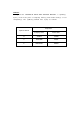
REMARK: Throughout this TECHNICAL DATA AND SERVICE MANUAL, a symbol(s) is(are) used in the place of company name(s) and model name(s) of our competitor(s).
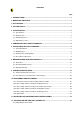
CONTENTS Page 1. PRODUCT NAME ..................................................................................................................... 1 2. MARKETING OBJECTIVE ....................................................................................................... 1 3. APPLICATIONS ........................................................................................................................ 1 4. SELLING POINTS ..........................................................................
1. PRODUCT NAME Hitachi 83 mm Coil Nailer, Model NV 83A2 2. MARKETING OBJECTIVE The current Model NV 83A is a well-reputed 3-1/4 coil nailer suitable for framing works. However, the coil nailer market is becoming increasingly competitive. The newly introduced Model NV 83A2 is developed by making minor changes to the current Model NV 83A to meet the market demands. The output section is common to that of the Model NV 83A featuring good driving response.
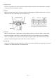
(1) Output section The basic construction is the same as that of the Model NV 83A except the 2-valve cylinder drive system that is well reputed for quick driving is adopted. (2) Adjuster While the Model NV 83A requires a wrench to adjust the nailing depth, the Model NV 83A2 requires no tool for adjustment. Amount of adjustment is about 4.5 mm (0.177").
5. SPECIFICATIONS 5-1. Specifications NV 83A2 Model Driving system Reciprocating piston type Operating pressure 5 --- 8.5 kgf/cm2 (70 --- 120 psi, 4.9 --- 8.3 bar) (Gauge pressure) Driving speed Min. 3 pcs./sec. Weight 3.7 kg (8.2 lbs.) Dimensions (Length x height x width) 290 mm x 348 mm x 135 mm (11-13/32" x 13-11/16" x 5-13/32") Nail feed system Reciprocating piston type Nail capacity 200 --- 300 nails (1 coil) Air consumption 2.4 ltr/cycle at 7 kgf/cm2 (.085 ft3/cycle at 100 psi) (2.
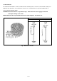
5-2. Nail Selection The Model NV 83A2 utilizes common round-head nails collated by wire or sheet into coils from 200 to 300 pieces. Applicable nail dimensions are shown below. However, it is recommended to use genuine HITACHI nails to ensure satisfactory driving quality. CAUTION: Ensure that nails are as specified in Fig. 1. Other nails will cause clogging of nails and subsequent damage to the nailer. NOTE: Aluminum nails may bend when driven into a hard workpiece. Test before use. Wire-collated nails Max.
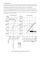
5-3. Nail Driving Force Fig. 2 shows by type of wood and nail, the nailer output energy provided by the supply pressure and the nailing energy required for driving the nail flush. Air pressure which exceeds the intersecting point between the nailer output energy and the nailing energy required for driving the nail allows the nail to be fully driven. For example, when driving a nail of 3.3 mm dia. by 83 mm length (0.
5-4. Optional Accessories Sequential trip mechanism kit (Single shot) (Code No. 876762) A sequential trip mechanism kit is provided as an optional accessory for the Model NV 83A2. By using this optional accessory, a nail is driven by pressing the pushing lever first against a workpiece and then pulling the trigger (single-shot operation), and no nail is driven when pulling the trigger first and then pressing the pushing lever against a workpiece.
--- 7 --- 8.4 lbs. (3.8 kg) 8.2 lbs. (3.7 kg) 8.2 lbs. (3.7 kg) Weight 2.5 mm -- 3.3 mm (0.098" -- 0.120") 50 mm -- 83 mm (2" -- 3-1/4") 2.5 mm -- 3.3 mm (0.098" -- 0.120") 50 mm -- 83 mm (2" -- 3-1/4") Shank dia. Length 38 mm -- 83 mm (1-1/2" -- 3-1/4") 2.5 mm -- 3.8 mm (0.098" -- 0.150") 38 mm -- 83 mm (1-1/2" -- 3-1/4") 2.5 mm -- 3.3 mm (0.098" -- 0.120") Wire Wire Wire Wire Applicable nails Rubber Rubber Rubber Racket grip Rubber Handle grip 50 mm -- 90 mm (2" -- 3-1/2") 2.
7. PRECAUTIONS IN SALES PROMOTION In the interest of promoting the safest and most efficient use of the Model NV 83A2 Nailer by all of our customers, it is very important that at the time of sale the salesperson carefully ensures that the buyer seriously recognizes the importance of the contents of the Instruction Manual, and fully understands the meaning of the precautions listed on the Warning Label attached to each tool. The Model NV 83A2 Nailer is designed for continuous nail driving.
7-3. Related Laws and Regulations As nailers and staplers are designed to instantaneously drive nails and staples, there is an ever-present danger of misfiring and subsequent possible serious injury. Accordingly, close attention in handling is absolutely necessary at all times. Carefully ensure that the customer is fully aware of the precautions listed in the Instruction Manual provided with each unit.
8. MECHANISM AND OPERATION PRINCIPLE 8-1. Mechanism As illustrated in Fig. 3, the Model NV 83A2 can be generally divided into four sections: output section, control valve section, driving section and magazine section. Although the output section and the valve section are basically common to those of the Model NV 83A, most of the parts of the driving section and the magazine section have been newly designed. Primary differences from the Model NV 83A are described below. Output section ...................
8-2. Interchangeability of Parts The driving section and the magazine section are not interchangeable between the Model NV 83A2 and the NV 83A because these sections of the Model NV 83A2 have been newly designed. The output section and the control valve section are interchangeable except the following parts. Part NV 83A2 NV 83A Pisotn Bumper (B) [29] 8.3 mm dia. 10 mm dia. Large hole dia. Hex. Socket Hd. Bolt (W/Flange) M6 x 45 [1] (for mounting the Top Cover [2]) Hex. Socket Hd.
Part NV 83A2 NV 83A Pushing Lever [54] Bent. Welded.
8-3. Operation Principle (1) When the compressed air source (air hose) is connected to the nailer: Air pressure is applied to the lower surfaces of the flanges located at the center portion of the cylinder, forcing the cylinder upward. The compressed air is thereby blocked from the upper end of the cylinder, and no pressure is applied to the Piston. The accumulator is filled with compressed air. The trigger and pushing lever are not operated, and remain closed.
(2) When the trigger and pushing lever are operated: Cylinder ring (D) Although air pressure is applied to both the upper and lower surfaces of the cylinder, the cylinder is forced downward due to the larger effective area of the upper surface. Accordingly, the upper portion of the cylinder is opened, and the compressed air forces the piston downward. (D) Compressed air is applied to the upper side of the exhaust valve, forcing it downward and closing the exhaust vent.
(3) If the trigger and pushing lever are kept pressed: Air pressure is applied in the shaded areas in the illustration, and each component is held in the position illustrated. If the operator's grip is loosened, air will leak. As there is no O-ring installed here, a very small amount of air will leak from the slight clearance between the components. The lower surface of the Piston contacts the Piston Bumper and prevents air leakage. If the upper surface of the damper is damaged, some air will leak. Fig.
(4) When the trigger and/or pushing lever are released: (C) The pressure on the upper surface of the exhaust valve is released, and the exhaust valve is pushed upward by the air pressure within the cylinder. This opens the exhaust vent, and the air pressure in the cylinder and the left-side surface of the feed piston are discharged from the nailer.
9. TROUBLESHOOTING GUIDE 9-1. Troubleshooting and Correction Problem 1) Nails cannot be driven. ( Possible cause : Most-common cause) Magazine is not loaded with specified genuine nails. Magazine is loaded with abnormal nails (bent nails, too large or too small nail heads, abnormal collation, others). Nails or link pieces are jammed. Link pieces are deformed or broken. Sliding resistance of the feed piston is too high.
Problem 1) Nails cannot be driven. (continued) ( Possible cause : Most-common cause) Inspection method Remedy Air leaks from Gasket (A). Tighten screws and replace gaskets. O-rings are worn or deformed. Replace the O-rings. O-rings need lubrication. Apply grease or lubricate. Nail guide face is abnormal (deformed, burrs or damaged). Dust sticks to the inside of the nail guide groove, or lubrication is needed.
Problem 1) Nails cannot be driven. (continued) ( Possible cause : Most-common cause) Inspection method Cylinder inside surface is abnormal (packed with dust, or worn). Check that nails can be driven at 5 kgf/cm2 (4.9 bar, 70 psi). Remove dust and then lubricate. Replace the part. Sliding surface between the cylinder and the cylinder guide or sliding surface between the cylinder and the cylinder plate is abnormal (seized or damaged, or lubrication is needed).
Problem 3) Nails cannot be driven into the workpiece completely: the heads cannot be made flush. (continued) Possible cause : Most-common cause) Inspection method Remedy Disassemble the output section and check inside and outside surfaces of the O-ring and the cylinder for abnormality. Replace the abnormal part. Check for shortage of grease on the sliding surface of the O-ring. Apply grease. Exhaust valve is abnormal or short of oil (worn or scratches on seat side).
Possible cause : Most-common cause) Unspecified nails are used. Abnormal nails are mixed. Nail heads are too large or too small. Collating wires are abnormal (broken, welding failed, deformed or welding position failed). Collating wires are deformed (deformed in collation angle or collation pitch). Inspection method Remedy Check if the specified nails are used. Check the nails as follows. Use specified nails. Remove the abnormal nails and load the nailer with proper nails. (1.4 76) 19 ( 0.
9-2.
Inspection priorities: In the table below, possible causes of air leakage and their repair procedures are marked in accordance with the likelihood of possible failure. (1) First priority items are marked with an asterisk ( ). (2) Second priority items (seal portions) are marked with a double circle ( (3) Remaining items are marked with a single circle ( name and location.) ). ).
Cause Air leak part When trigger valve/safety valve are OFF Between feed piston cover and nose When trigger valve ON/ safety valve OFF Defective O-ring [69] of Feed Piston [70] (worn, deformed or cut) Defective Feed Piston [70] sliding portion (damaged, deformed or broken) H Feed piston I When trigger valve/ safety valve are ON Defective seal surface of Tail Cover [31] and Feed Piston Cover [75] Defective O-ring [71] of Feed Piston [70] (worn, deformed or cut) Slight amount of air is always leaked ou
10. DISASSEMBLY AND REASSEMBLY The items particularly necessary for disassembly and reassembly are described below. The [Bold] numbers in the descriptions below correspond to the item numbers in the Parts List and exploded assembly diagram. [CAUTION] Before disassembly or reassembly, be sure to remove all nails and disconnect the air hose from the nailer (with your finger released from the trigger) to exhaust all the compressed air. 10-1.
10-2. Disassembly and Reassembly of the Output Section (1) Piston (H) [12], Cylinder [17] and related parts Tool required: Hexagon bar wrench (5 mm) (a) Disassembly (See Figs. 10, 11 and 12.) Remove the four Hex. Socket Hd. Bolts (W/Sp. Washer) M6 x 25 [3], and take off the Exhaust Cover [4]. The Piston (H) [12] can then be taken out. Next, as illustrated in Fig. 9, screw two of the previously removed Hex. Socket Hd. Bolt (W/Sp. Washer) M6 x 25 [3] into the provided holes on the Cylinder Plate [15].
O-Ring [11] Cylinder Spring [20] Piston (H) [12] Base Washer [21] Cylinder Guide [22] Gasket (G) [23] Cylinder Plate [15] Body (B) [27] Cylinder [17] Cylinder Ring [19] Fig. 10 (2) Head Cap and Gasket Set [10], Exhaust Piece [7] and related parts (See Fig. 11.) Tool require: Hex. Socket Hd. Bolt (W/Flange) M6 x 45 [1] Hexagonal bar wrench (5 mm) (a) Disassembly Remove the Exhaust Cover [4] as described in Top Cover [2] section 10-2-(1). Loosen the three Hex. Socket Hd. Bolts (W/Flange) Hex.
10-3. Disassembly and Reassembly of the Control Valve Section Tool required: Roll pin puller (3 mm (0.118") dia.) Minus-hd. screwdriver (a) Disassembly (See Fig. 12.) Remove the Magazine [81] as described in section 10-4. Remove the Pushing Lever [54] as described in section 10-5. With the roll pin puller (3 mm (0.118") dia.), take out the Roll Pin D3 x 30 [63], and remove the Trigger [62], Trigger Plunger [68] and Safety Plunger (B) [61]. Insert the minus-hd.
10-4. Disassembly and Reassembly of the Magazine Section Tools required: Phillips screwdriver Roll pin pullers (4 mm dia., 2.5 mm dia.) Hex. bar wrench (4 mm) Wrench M5 (1) Disassembly and reassembly of the magazine section (a) Disassembly (See Fig. 15.) Loosen the Hex. Socket Hd. Bolt M5 x 20 [100] and the Nylon Nut M5 [78] then remove the Sleeve [79]. Deform Guard [80] using a flat-blade screwdriver and disengage it from the Tail Cover [31]. Loosen the Machine Screw M5 x 25 [44] of the Body (B) [27].
(b) Reassembly Disassembly procedures should be followed in the reverse order. Note the following points. Bend the tip of the Cover [105] and engage it with the convex portion of Magazine [81]. Hold it with Guard [80] positioning the Cover [105] outside Guard [80]. Nylon Nut M5 [78] Body (B) [27] Magazine [81] Pin [82] Feeder Shaft Ring [83] Nylon Nut M5 [78] Pin [82] Magazine Cover [84] Sleeve [79] Guard [80] Concave portion Machine Screw M5 x 25 [44] Hex. Socket Hd.
(2) Disassembly and reassembly of nail holder, holder shaft, etc. (a) Disassembly Pull out the two Pins [82] with a roll pin puller (4 mm dia.). Then Magazine [81] and Magazine Cover [84] can be removed. Remove Holder Cap [85] and Roll Pin D2.5 x 18 [88] with a roll pin puller (2.5 mm dia.). Then Nail Holder [87], Holder Shaft [89] and Spring [90] can be removed. (b) Reassembly Disassembly procedures should be followed in the reverse order. Note the following points.
10-5. Disassembly and Reassembly of the Driving Section Safety Plunger (B) [61] Body (B) [27] Seal Lock Hex. Socket Hd.
(1) Tail Cover [31], Pushing Lever [54] and the related parts (See Fig. 17.) Tools required: Hexagon bar wrench (6 mm) Roll pin puller (3 mm (0.118") dia.) Screwdriver (a) Disassembly Pull out the Roll Pin D3 x 45 [53]. Then Valve Guard [52] can be removed. Remove the four Nylock Hex. Socket Hd. Bolts M8 x 22 [37]. Then Piston Bumper (B) [29], Gasket (A) [30] and Pushing Lever [54] can be removed together with the Tail Cover [31].
(2) Disassembly and reassembly of Piston Bumper (B) [29], Feeder Set [35], Feed Piston [70] and other parts (See Fig. 24.) Tools required: Flat-blade screwdriver Hexagon bar wrench (4 mm, 6 mm) Roll pin puller (3 mm (0.118") dia.) (a) Disassembly (See Fig. 17.) Remove the two Seal Lock Hex. Socket Hd. Bolts M5 x 10 [76] from the Tail Cover [31]. The Feed Piston Cover [75], Feed Piston Cover (A) [74], Feed Spring [72] and Bumper [73] can then be removed.
(4) Disassembly and reassembly of Nail Guide [95], Sub Nail Stopper [92], Feeder Set [35] and other parts (See Fig. 19.) Tools required: Flat-blade screwdriver Hex. bar wrench 3 mm Roll pin puller (3 mm (0.118") dia.) (a) Disassembly Remove the Shaft Ring [91] from the Nail Guide Shaft [101] with a flat-blade screwdriver and remove the Nail Guide Shaft [101]. Then the Nail Guide [95] and other parts can be removed in an assembly. Remove the Seal Lock Hex. Socket Hd. Bolt M4 x 8 [107] with a hex.
(b) Reassembly Disassembly procedures should be followed in the reverse order. Note the following points. Before reassembly, remove dust from the groove of the Nail Guide [95]. Fit the convex portions of Sub Nail Stopper [92] and Feeder Set [35] in the Sub Stopper Spring [93] and Main Stopper Spring [103] securely. Be careful not to mistake Sub Stopper Spring [93] for Main Stopper Spring [103].
11. INSPECTION AND CONFIRMATION AFTER REASSEMBLY Check that Safety Plunger (B) [61] and Trigger Plunger [68] move smoothly. Check that there is no air leakage from each part. While driving nails with an air pressure of 4.5 kgf/cm2 (63 psi), check that there is no idle driving and bending of nails. Note: Before conducting the driving test, turn Adjuster [39] to the deepest position. Recheck the tightening torque of each screw. Check that Pushing Lever [54] slides smoothly.
12. STANDARD REPAIR TIME (UNIT) SCHEDULES MODEL Variable Fixed 10 20 30 40 50 60 min.
LIST NO.
PARTS ITEM NO. 1 * * NV 83A2 CODE NO. NO. USED DESCRIPTION 883-509 HEX. SOCKET HD. BOLT (W/FLANGE) M6X45 2 877-330 TOP COVER 1 3 883-507 HEX. SOCKET HD. BOLT (W/SP.
PARTS ITEM NO. 51 NV 83A2 CODE NO. NO. USED DESCRIPTION 875-650 SAFETY BOLT 1 52 884-027 VALVE GUARD 1 53 884-025 ROLL PIN D3X45 1 54 884-026 PUSHING LEVER 1 55 949-555 NUT M5 (10 PCS.) 1 56 875-643 PLUNGER SPRING 1 57 884-039 PLUNGER (A) 1 58 874-820 PLUNGER O-RING 2 59 875-638 O-RING (S-12) 3 60 878-266 VALVE BUSHING 1 61 875-642 SAFETY PLUNGER (B) 1 62 876-203 TRIGGER 1 63 949-866 ROLL PIN D3X30 (10 PCS.
NV 83A2 PARTS ITEM NO. 102 CODE NO. 949-865 NO. USED DESCRIPTION ROLL PIN D3X28 (10 PCS.) REMARKS 1 103 876-681 MAIN STOPPER SPRING 1 104 877-469 NAIL GUIDE COVER 1 105 884-023 COVER 1 106 884-022 PLATE 1 107 877-838 SEAL LOCK HEX. SOCKET HD. BOLT M4X 8 2 108 884-032 MAGAZINE ASS’Y 1 INCLUD. 81-90 STANDARD ACCESSORIES ITEM NO. 501 CODE NO. NO. USED DESCRIPTION REMARKS 872-422 HEX. BAR WRENCH 6MM 1 502 944-459 HEX. BAR WRENCH 5MM 1 503 944-458 HEX.