
User manual

MRD 3187B User Manual
Page 14
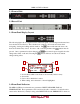
2.1 Front of Unit
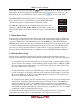
2.2 Rear of Unit
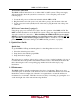
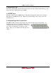
2.3 Front Panel Display Layout
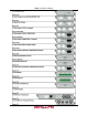
The following figure shows a typical screen on the front panel. Several important features have
been circled and noted below. These features are common to all screens and assist when
navigating, viewing and editing unit information. The button will return the user to the
home level while in any screen. In order to edit a selected parameter, the button must be
pressed. Once a parameter has been changed, the button must be pressed again before the
change takes effect on the unit. Pressing the button will leave an edit mode without
changes taking effect.
1. Icons indicate which control buttons are currently valid for entry.
2. Screen title.
3. Cursor shows which line is active.
4. When editing, active character or item is highlighted.
2.4 Front Panel Indicators
The MRD 3187B has four internal error parameters: INPUT, DECODER, FAN and
TEMPERATURE. These parameters can be monitored locally or remotely. Locally the unit’s
status can be checked by visually looking at the INPUT LED and the ERROR LED on the front
RDS1 Serv Setup
Tune Mode:PID Lock
PID Select:Manual
►PCR PID :0x0031
1
3
1
4
2