G.hn over Coax Wi-Fi Gb Ethernet Bridge User’s Guide V1.
INTRODUCTION This G.hn to Wi-Fi Gb Ethernet bridge connects any wireless and Ethernet devices to a high speed connection of the coax network for Internet access. This bridge brings you the newest Ethernet compatible technology that uses the coaxial cable as the network's physical wiring thereby eliminating the need to install new wiring in a residential environments. It is designed to operate on the coaxial cable network.
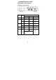
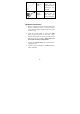
HARDWARE INSTALLATION Parts Names and Functions LED Indicators on the Rear Panel Port LED DC 12V PWR LAN1 LAN2 Flashing Link Act Powered by N/A DC12V Receive Link Transmit 1000 1000Mbps N/A Link Act Link Receive Transmit 1000 1000Mbps N/A WiFi Link Link Act G.
Ports on the Rear Panel Port Name Type A DC 12V DC B LAN1/LAN2 RJ-45 C R Functions Connect to the power adapter plug. Connect to PC or STB or other Ethernet devics. Factory Reset Button D TV F Connect to TV E G.hn F Connect to G.hn devices Essential Hardwares Items Included Description Purpose G.hn to WiFi GbE Bridge Main Unit Coaxial Cable (F-Type/ RG-59U or RG-6) Connects from G.hn port to coax F-Type connector on the wall outlet.
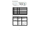
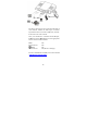
CAT5 Ethernet cable Connects from LAN port to Ethernet enabled devices as PC or STB DC12V Power adapter Connects from Power port of the main unit into a wall outlet Hardware Connections 1. Select a convenient location for the bridge near the PC or Ethernet device to which it will be connected. The bridge should be kept away from excessive heat. 2. Using one coaxial cable to connect the G.hn port to F-Type connector on the wall.
The figure above shows the connection diagram of coax network. Follow the same steps to connect any Ethernet devices such as a STB or PC, and WiFi devices to the coax network. Now you should have connected the LAN port, G.hn port and the DC 12V port to the appropriate devices or lines. LED will be as: PWR LAN Link/Act (WiFi) G.
TROUBLESHOOTING The bridge has been designed to be a reliable and easy to use connection device. Please refer to the list below to aid in troubleshooting. The Power (green PWR) LED is off. Make sure the power adapter is properly plugged into a live electrical outlet. The LAN(Ethernet) LED is off. Make sure the connection to LAN port is secure. The Ethernet device to which you are connected should be powered on and properly configured. The G.
SPECIFICATIONS Standards IEEE 802.3u 100BaseT Fast Ethernet IEEE 802.3ab 1000BaseT Gigabit Ethernet IEEE 802.11b/g/n/a/ac compliant ITU-T G.9960/G.9961 G.hn over Coax Data Rates G.hn: 2Gbps (6-200MHz / Filter 216MHz) Ethernet: 100 /1000 Mbps Wi-Fi : 866M(5GHz)/300Mbps(2.4GHz) max Transmission Range G.
Federal Communications Statement Commission (FCC) You are cautioned that changes or modifications not expressly approved by the part responsible for compliance could void the user’s authority to operate the equipment. This equipment has been tested and found to comply with the limits for a Class B digital device, pursuant to part 15 of the FCC rules. These limits are designed to provide reasonable protection against harmful interference in a residential installation.
-Consult the dealer or an experienced radio/TV technician for help. For product available in the USA/Canada market, only channel 1~11 can be operated. Selection of other channels is not possible. Operations in the 5.15-5.25GHz band are restricted to indoor usage only. This device meets all the other requirements specified in Part 15E, Section 15.407 of the FCC Rules. This device complies with Part 15 of the FCC Rules.
co-located or operating in conjunction with any other antenna or transmitter.