
User's Guide

- 5 -
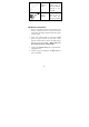
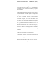
The figure above shows the connection diagram of
coax network. Follow the same steps to connect
any Ethernet devices such as a STB or PC, and Wi-
Fi devices to the coax network.
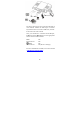
Now you should have connected the LAN port,
G.hn port and the DC 12V port to the appropriate
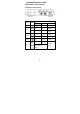
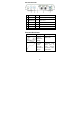
devices or lines. LED will be as:
PWR ON
LAN Link/Act ON
(WiFi) ON
G.hn Link/Act ON (Green or Orange)
For more information on LEDs, see section entitled
"
LED Indicators on the Rear Panel"