
Submittal Sheet

Page
:
5 of 8
Document No.U085167
Date
:
Nov/20/2019
INSTALLATION
The Model RC-RES must be installed in accordance with the following instructions:
NOTES
Do not use any sprinklers which have been subjected to potential mechanical damage. Do not use any sprinklers which
show deformation or cracking in either the Sprinkler or the Protective Cap.
Prior to installation, sprinklers should be maintained in the original cartons and packaging until used to minimize the
potential for damage to the sprinklers that could cause improper operation or non-operation.
The Protective Cap must remain on the sprinkler during installation. After the installation is completed, the Protective
Cap must be removed to place the sprinkler in service.
Use a torque of 7 to 14 ft·lbs (9.5 to 19.0 N·m) to achieve a 1/2 inch NPT sprinkler joint. If you exceed the recommended
maximum torque, this could result in damage to the sprinkler inlet, which may lead to leakage from the sprinkler.
Use only NR-H model wrench socket for installation of RC-RES sprinklers. Use of any other wrench or socket is
prohibited and may cause damage to the sprinkler.
In case of insufficient adjustment in Cover Plate installation, do not try to overly tighten, screw the sprinkler too loosely
or make any modification to the cover plate assembly. Readjust the sprinkler fitting for a better fit.
Do not rotate the Cap Remover RC to the left with force when placing the two hook arms into place. The installed
sprinkler may become loosened, which may cause water leakage.
Installing Procedure
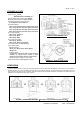
Step 1
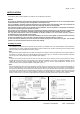
The installation requirements for the sprinkler are as follows: to be installed only in the pendent position with the waterway
perpendicular to the ceiling. Install the sprinkler fitting so that the distance from the face of the fitting to the mounting surface
will be nominally 2 inches (50.8mm) as shown in Figure 3.
Step 2
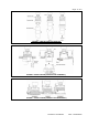
With pipe thread sealant applied to the threads, hand tighten the sprinkler into the sprinkler fitting. Then tighten it with the
Socket NR-H or Ratchet (3/8” drive) & Socket NR-H Combination (Ref. Figure 4). The teeth of the Socket must fit perfectly
with the grooves on the Sprinkler for proper installation (Ref. Figure 4).
Step 3
If desired, the Protective Cap may also be used to locate the center of the clearance hole by gently pushing the ceiling
material against the center point of the Protective Cap. Before the installation of the ceiling, the sprinkler installation can be
started with a 2-3/8 inch (60mm) diameter clearance hole (Ref. Figure 3). Use the “Vertical Adjustment” indicator on the
Protective Cap to check for proper installation height (Ref. Figure 3).
Step 4
Use the Cap Remover RC to remove the Protective Cap (Ref. Figure 5), and then push or screw a Cover Plate Assembly on
the Cup of the Sprinkler by hand until its flange just has contact with the ceiling (Ref. Figure 6 and Figure 7). Stop tightening
the Cover Plate Assembly once the flange has contact with the ceiling. If the ceiling has been lifted from its normal position in
the process of tightening the Cover Plate Assembly, readjust the cover plate assembly as necessary. If the flange of the Cover
Plate Assembly cannot contact the ceiling sufficiently, readjust the sprinkler fitting as necessary. When properly installed,
there is a nominal 1/16 inch (1.6mm) air gap between the lip of the Cover Plate and the ceiling, as shown in Figure 6.
FIGURE 3. INSTALLATION
FIGURE 4.
RATCHET & SOCKET