
Manual


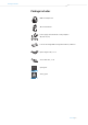

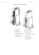

Table Of Contents
- Important safety information
- The RS 185 digital wireless headphone system
- Package includes
- Product overview
- Putting the RS 185 into operation
- Using your RS 185 headphone system
- Cleaning and maintaining the RS 185
- Troubleshooting
- Specifications
- Manufacturer declarations

Product overview
RS 185 | 9
Overview of the TR 185 transmitter
1 TR status LED
MLC
ALC
LEVEL
MLC
MAX
MIN
6
2
1
4
5
3
7
8
9
0
2 MLC rotary knob,
for manual level control
adjustment
3 ALC, MLC LEVEL LEDs, indicate
the selected signal level control
4 LEVEL button
to toggle between manual and
automatic level controls
5 Charge status LED
6 Charging contacts
7 DIGITAL OPTICAL IN Digital
optical audio input
8 AUDIO INPUT SELECTION switch,
for digital or analog audio input
selection
9 L, R RCA audio input,
for analog audio input
0 DC 9V 0.3A socket for the
power supply unit