
User's Manual

EN Product overview
4|RS 5000
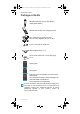
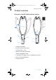
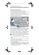
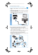
Overview of the TR 5000 transmitter
1
Battery
LED ,
indicating the charging process/remaining operating time
of the stethoset receiver (see page 11 and 12)
2 Balance buttons for the right ear R and the left ear L
3 Hearing profile button
for selecting the hearing profiles (see page 18)
4 Hearing profile LED ,
indicating the activated hearing profile (see page 18)
5 Charging compartment for stethoset receiver
6 Charging contacts for stethoset receiver with holding
magnets
7
Transmitter status
LED (see page 5)
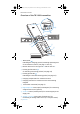
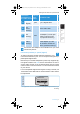
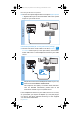
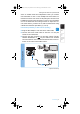
8 Digital Optical In audio input (marked pink) for connecting
a digital audio source (optical)
9 5V DC 1A socket (marked yellow) for connecting the power
supply unit
0 Analog 3.5 mm In audio input (marked blue) for
connecting an analog audio source (3.5 mm jack socket)
5
4
2
6
7
1
2
3
0
98
1A
RS_5000_570727_0117_PRT.book Seite 4 Montag, 10. Oktober 2016 2:52 14