Active Transmitter Combiner 8:1 AC 3200 Instruction manual
Contents Contents Important safety instructions ..................................................... 2 The AC 3200 active transmitter combiner 8:1 ......................... 5 Delivery includes ............................................................................. 5 Connection diagram ....................................................................... 6 Product overview ............................................................................ 7 Putting the AC 3200 into operation .............
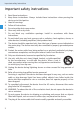
Important safety instructions Important safety instructions 1. 2. 3. 4. 5. 6. 7. 8. 9. 10. 11. 12. 13. 14. 15. 16. 17. 18. 2 Read these instructions. Keep these instructions. Always include these instructions when passing the device on to third parties. Heed all warnings. Follow all instructions. Do not use the device near water. Clean only with a dry cloth. Do not block any ventilation openings. Install in accordance with these instructions.
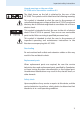
Important safety instructions Hazard warnings on the rear of the AC 3200 active transmitter combiner 8:1 The label shown on the left is attached to the rear of the AC 3200. The symbols on this label have the following meaning: This symbol is intended to alert the user to the presence of uninsulated dangerous voltage within the AC 3200’s enclosure that may be of sufficient magnitude to constitute risk of fire or electric shock.
Important safety instructions Intended use of the device Intended use of the AC 3200 includes: y using the device for professional purposes, y having read this instruction manual especially the chapter “Important safety instructions” on page 2, y using the device within the operating conditions and limitations described in this instruction manual. “Improper use” means using the device other than as described in this instruction manual, or under operating conditions which differ from those described herein.
The AC 3200 active transmitter combiner 8:1 The AC 3200 active transmitter combiner 8:1 With the AC 3200 active transmitter combiner, the signals of up to eight Sennheiser wireless monitoring transmitters can be combined onto a single antenna, e.g. the A 2003 UHF directional antenna, the A 1031 U omni-directional antenna or the A 5000 CP circularly polarized UHF antenna. For suitable transmitters, please refer to the AC 3200 product page at www.sennheiser.com.
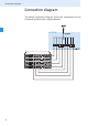
Connection diagram Connection diagram The below connection diagram shows the connections for an 8-channel system with a single antenna.
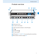
Product overview Product overview 쐋 쐇 쐏 쐃 쐄 쐇 쐃 70 W 쐂 쐆 쐆 쐊 쐆 쐆 쐃 Rack mount “ears” 쐇 Air vents (on the sides) 쐋 8 LEDs: operation indicators of the RF inputs 쐏 LED 쐄 On/off switch 쐂 IEC mains socket 쐆 8 RF inputs RF IN 1 to RF IN 8 for connecting the transmitters 쐊 BNC socket for antenna output ANT 7
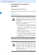
Putting the AC 3200 into operation Putting the AC 3200 into operation Preparing the AC 3200 for use You can set up the AC 3200 on an even surface or mount it into a 19" rack.
Putting the AC 3200 into operation 왘 Ensure that the base of the AC 3200 is clean and free from grease before fitting the rubber feet. 왘 Fix the rubber feet to the base of the AC 3200 by peeling off the backing paper and fitting them as shown in the diagram on the left. 왘 Place the AC 3200 on an even, horizontal surface.
Putting the AC 3200 into operation To mount the AC 3200 into a 19" rack: 왘 Slide the AC 3200 into the 19" rack. 왘 Secure the rack mount “ears” 쐃 to the rack using four screws (not included). Connecting the antenna CAUTION! Danger of damage to the devices! Do not daisy-chain several AC 3200. Do not connect other active combiners to the AC 3200. 왘 Never connect the AC 3200 to other active combiners.
Putting the AC 3200 into operation 쐆 쐆 쐆 쐆 70 W Connecting the mains cable 왘 Connect the suitable mains cable to the IEC mains socket 쐂 and to the mains. Note: 70 W The AC 3200 can be connected to any mains power supply with 100 V to 240 V AC (50 to 60 Hz). Switching the AC 3200 on and off 쐋 쐏 쐄 왘 Press the on/off switch 쐄. The AC 3200 switches on and the LED 쐏 lights up red. 왘 Press the on/off switch 쐄 again. The AC 3200 switches off and the LED 쐏 goes off.
Recommendations and tips for optimum reception Recommendations and tips for optimum reception y There should be a “free line of sight” between transmitting and receiving antennas. y To avoid overloading the receiver, observe a minimum distance of 5 m between transmitting and receiving antennas. y Observe a minimum distance of 50 cm between the transmitting antenna and metal objects (such as cross members or reinforced-concrete walls).
If a problem occurs ... If a problem occurs ...
Accessories and spare parts Accessories and spare parts The following accessories are available from your Sennheiser partner: Cat. No.
Specifications Specifications Frequency range 500 – 870 MHz Distribution attentuation 0 dB (±1 dB) RF input power nominal value up to 100 mW per input inputs protected up to max. 250 mW Impedance 50 Ω Power supply 100 V – 240 V AC, 50 – 60 Hz Power consumption max. 70 W Temperature range 0 °C to 45 °C Weight approx. 4 kg Type approvals Area Conformity USA: FCC-Part 74.
Manufacturer Declarations Manufacturer Declarations Warranty Sennheiser GmbH & Co. KG gives a warranty of 24 months on this product. For the current warranty conditions, please visit our web site at www.sennheiser.com or contact your Sennheiser partner. CE Declaration of Conformity 0682 This equipment is in compliance with the essential requirements and other relevant provisions of Directives 1999/5/EC and 2006/95/EC. The declaration is available on the internet site at www.sennheiser.com.
Sennheiser electronic GmbH & Co. KG Am Labor 1, 30900 Wedemark, Germany Phone: +49 (5130) 600 0 Fax: +49 (5130) 600 300 www.sennheiser.com Printed in Germany Publ.