
ADN System Instruction Manual


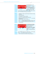
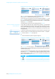


Table Of Contents
- Important safety instructions
- The Sennheiser ADN conference system
- Available system components – package contents
- Overview of the components
- ADN D1 delegate unit
- ADN C1 chairperson unit
- ADN-W D1 wireless delegate unit
- ADN-W C1 wireless chairperson unit
- ADN-W BA Lithium-Ion battery pack
- ADN-W MIC 15/ADN-W MIC 36 gooseneck microphones for wireless conference units
- ADN-W AM antenna module
- NT 12-50C power supply
- ADN CU1 central unit
- “Conference Manager” software
- ADN PS power supply
- SDC CBL RJ-45 system cables
- ADN-W L 10 charger
- ADN-W CASE transport and charging case
- Structuring and controlling the conference system
- Number of chairperson and delegate units
- Calculating the voltage supply of the wired conference units and system components
- Setting up a wired conference system
- Setting up a wireless conference system
- Combining wired and wireless conference units (hybrid operation)
- Configuring and controlling the conference system
- Input and output of audio signals
- Integration into a media control system
- Using the ADN Cable Calculator software
- Putting the conference system into operation
- Preparing the ADN CU1 central unit for operation
- Preparing the ADN PS power supply for operation
- Preparing the ADN-W AM antenna module for operation
- Preparing the ADN C1/ADN D1 wired conference units for operation
- Preparing the ADN-W C1/D1 wireless conference units for operation
- Preparing the ADN-W L 10 charger for operation
- Preparing the ADN-W CASE UNITS charging case for operation
- Charging the ADN-W BA battery pack
- Checking the charge status of the battery pack
- Charging the battery pack using the NT 12-50C power supply
- Simultaneously charging up to 10 battery packs in the ADN-W L 10 charger
- Simultaneously charging up to 10 battery packs in the ADN-W CASE UNITS charging case
- Switching off the ADN-W L 10/ADN-W CASE UNITS charger
- The status display of the ADN-W L 10/ADN-W CASE UNITS charger during charging
- Behavior of the ADN-W BA battery pack during charging
- Setting up the conference system
- Basic information on the set-up of the conference system
- Setting up a small wired conference system with only the central unit
- Setting up a large wired conference system with ADN PS power supplies connected to the ADN CU1 central unit
- Setting up a large conference system comprising ADN PS power supplies and conference units connected in cable strings
- Setting up a large conference system comprising ADN PS power supplies and conference units connected in redundant ring topology
- Cabling errors
- Connecting the ADN-W AM antenna module to the ADN CU1 central unit
- Setting up and positioning the antenna module
- Setting up the ADN-W C1 or ADN-W D1 wireless conference units
- Connecting external audio devices to the central unit
- Connecting a USB mass storage device for audio recordings to the central unit
- Preparing to use the “Conference Manager” software
- Switching the conference system on/off
- Using the media control system
- Configuring the wireless components
- Using the central unit
- Configuring the conference system via the central unit
- Overview of the operating menu
- Working with the operating menu
- Adjusting the conference settings – “Conference Menu”
- Setting the conference mode – “Conference Mode”
- Setting the max. number of speakers who can take the floor simultaneously – “Microphone Limit”
- Setting the maximum number of requests to speak – “Request Limit”
- Activating/deactivating the speaking time limit – “Talk Time Status”
- Setting the speaking time limit– “Talk Time Limit”
- Setting the advance warning time – “Premonition Time Limit”
- Determining the behavior when the individual speaking time is exceeded – “Reaction on Talktime Exceed”
- Activating/deactivating the flashing of the signal light ring when a request to speak is made – “Blink on Request”
- Re-initializing the conference units – “Re-Init”
- Setting the function of the priority key – “Clear Request List on Cancel”
- Adjusting the radio settings – “Wireless Menu“
- Adjusting the audio settings – “Audio Menu”
- Adjusting settings for the OUT audio output and the IN audio input – “XLR Out” and “XLR In”
- Adjusting settings for the floor channel – “Floor/Loudspeakers”
- Adjusting the processing of the conference units’ audio signals in the floor channel – “Audio Gain Reduction”
- Activating/deactivating the function for eliminating feedback and for increasing the volume – “Feedback Suppression“
- Activating/deactivating the filtering of the IN audio input from the OUT audio output (avoiding echoes) – “XLR Mix Minus”
- Activating/deactivating the conference units’ built-in loudspeakers for contributions coming from the conference units’ microphones – “Mic Loudspeaker Mute“
- Activating/deactivating the recording of the conference on a USB mass storage device and viewing the status of the recording – “Conference Recording“
- Checking the system and detecting errors – “System Menu”
- Adjusting the language – “*Language”
- Adjusting further settings – “Settings”
- Running a conference
- Using the “Conference Manager” software
- Possibilities of usage of the software and the conference system
- Preparing the central unit’s integrated software for use
- Preparing the Windows version of the software for use
- System requirements
- Installing the “Conference Manager” software
- Uninstalling the “Conference Manager” software
- Adjusting the network settings
- Configuring the network settings on a PC running Windows XP
- Configuring the network settings on a PC running Windows Vista
- Configuring the network settings on a PC running Windows 7
- Configuring the network settings on a PC running Windows 8
- Starting/exiting the software
- Getting to know and adjusting the basic features of the software
- Overview of the software
- Menu bar
- Buttons for selecting the views
- Toolbar
- Buttons for selecting the operating mode
- Selecting operating modes and views
- Adjusting the View windows to your needs
- Adjusting the screen, mouse, and keyboard settings and the date/time setting of the central unit
- Adjusting the language
- Using a password
- Adjusting network settings
- Loading the factory default settings
- Switching off all connected wireless conference units
- Using the conference system and the software
- Connecting the software to the central unit
- Disconnecting the connection to the central unit
- Creating a new configuration
- Loading a configuration
- Activating/deactivating automatic loading of a configuration
- Eliminating connection problems when a configuration is autoloaded
- Saving a configuration
- Closing a configuration
- Deleting a configuration from the central unit
- Configuring the settings for wireless conferencing
- Calling up the general radio settings
- Selecting the country-specific settings – “Country Selection“
- Setting the RF channel – “Channel Selection“
- Setting the RF signal strength – “Output Power“
- Logging in the wireless conference units to the conference system – “Access Mode“
- Calling up the settings for logging in the wireless conference units
- Automatically logging in the wireless conference units (open wireless conferencing) – “Access Mode - Open“
- Manually logging in the wireless conference units (closed wireless conferencing) – “Access Mode - Closed“
- Deactivating manual switch-off of the wireless conference units – “Enable Wireless Unit shutdown“
- Preparing a conference and mapping a conference room – “Setup” operating mode
- Initializing the conference units – “Setup” operating mode
- Adjusting the conference settings – “Setup” operating mode
- Controlling and monitoring a conference – “Live” operating mode
- Adding conference units to the conference system during operation
- Adjusting settings during a running conference
- Changing the view of the canvas
- Setting the volume of the conference units’ built-in loudspeakers
- Activating/deactivating the audio input/output
- Activating/deactivating the speaking time limit
- Changing the conference mode
- Changing the maximum number of speakers who can take the floor simultaneously
- Changing the maximum number of requests to speak
- Changing the behavior of the signal light ring when a request to speak is made
- Recording a conference
- Exiting “Live” operating mode
- Recording a conference – “Conference Recording”
- Using the log and diagnosis function – “Event Log”
- Cleaning and maintaining the conference system
- Transporting the wireless components
- Updating the firmware of the conference system
- If a problem occurs .../Frequently asked questions
- Components and accessories
- Specifications
- Appendix
- Manufacturer Declarations
- Index – ADN conference system
- Index – “Conference Manager” software

ADN Digital Conference System | 109
Configuring the conference system via the central unit
To prevent an increase in temperature:
왘 Make sure that the air vents of the ADN CU1 central unit and the ADN PS power
su
pplies are not covered or blocked (see page 38 and page 40).
왘 If necessary, clean the air vents (see page 225).
If the ADN
CU1 central unit and the ADN PS power supplies are mounted into a rack:
왘 Provide additional ventilation by providing for
a
duct or vent space of 1 U below
and above the central unit and the power supplies and/or by installing addi-
tional fans into the rack.
When the temperature is again within the permissible temperature range, this is
automatically detected by the system (the icon appears behind “System” on the
display). The temperature check is carried out cyclically.
If, in spite of these measures, the temperature is still detected to be too high, one
of the fans might be faulty:
왘 Have the fans checked and, if necessary, replaced by qualified maintenance
pe
rso
nnel.
Displaying system bus errors –
“Bus
Statistics”
Possible causes for system bus errors are:
• c
hanges in the number of conference units
• faulty cables
• faults in cable shields
• faulty conference units/faulty antenna module
• strong electromagnetic fields
If there are system bus errors, the icon appears behind “Error Indication”. The
d
isplay panel lights up red and the warning triangle is displayed on the standard
display (see page 102).
There are temporary or permanent transmission errors:
Temporary transmission errors can be caused by e.g. poorly shielded mobiles
phones
that are pl
aced too close to the system cables, the conference units or the
antenna module. If the transmission error no longer exists, the icon appears on
the display. The display panel lights up orange and the warning triangle goes
off.
Permanent transmission errors must be el
iminat
ed immediately in order to ensure
trouble-free operation of your conference system. Follow the steps for error elimi-
nation described under the “System Load” menu item (see page 107). If necessary,
reduce the length of the system cables between the ADN CU1 central unit and the
ADN PS power supplies (shorter cables increase the operational reliability, the
maximum length allowed is 50 m). In addition, check if other electronic devices in
the vicinity of the conference system might cause the errors.
You can manually reset the icon behind “Error Indication” to the default icon ( )
(see page
111).
The error counter (“Break Counter”) incrementally counts al
l
errors and changes in
the conference system (e.g. added conference units or connected and switched on
ADN PS power supplies). Based on the changes of the counter’s counts, you can
conclude on the error source (e.g. if the counter rapidly increments when you
wiggle the cable, this indicates a faulty cable).
You can manually reset the error counter (“Break Counter”) (see page 110).
Select and call up the
“Diagnostics” submenu
Select and call up the
“Bus Statistics” menu
item
View the information;
exit the menu item
Diagnostics
System Load
Temperature
Bus Statistics
Bus Statistics
No No
Main Menu
System Menu
Diagnostics
Error Indication : ☺
Break Counter : 1
N
N