
Instruction manual - 2000 IEM Series
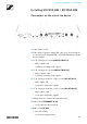
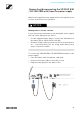

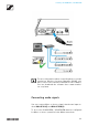


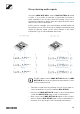

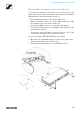
Table Of Contents
- Product information
- Products of the 2000 IEM series
- Accessories
- The frequency bank system
- Installing 2000 IEM series devices
- Installing the EK 2000 IEM
- Installing SR 2000 IEM / SR 2050 IEM
- Connectors on the rear of the device
- 1 3-pin mains socket
- 2 Cable grip for power supply DC cable (see Connecting/disconnecting the SR 2000 IEM / SR 2050 IEM with/from the power supply).
- 3 ¼" (6.3 mm) jack socket LOOP OUT BAL L(I)
- 4 ¼" (6.3 mm) jack socket LOOP OUT BAL R(II)
- 5 ¼" (6.3 mm) jack/XLR-3 combo socket BAL AF IN L(I)
- 6 ¼" (6.3 mm) jack/XLR-3 combo socket BAL AF IN R(II)
- 7 LED (yellow) for network activity indication
- 8 LAN socket (ETHERNET RJ 45)
- 9 BNC socket RF OUT
- Connecting/disconnecting the SR 2000 IEM / SR 2050 IEM with/from the power supply
- Creating a data network
- Connecting audio signals
- Daisy chaining audio signals
- Connecting antennas
- Mounting the transmitter into a rack
- Connectors on the rear of the device
- Installing the AC 3200-II
- Using 2000 IEM series devices
- Using the EK 2000 IEM
- Operating elements of the EK 2000 IEM diversity receiver
- Switching the EK 2000 IEM
- Lock-off function
- Displays on the EK 2000 IEM display panel
- Buttons for navigating through the menu
- Home Screen
- Setting options in the menu
- Menu structure
- Squelch menu item
- Easy Setup menu item
- Frequency Preset menu item
- Name menu item
- Balance menu item
- Mode menu item
- High Boost menu item
- Auto Lock menu item
- Advanced menu item
- Advanced -> Tune menu item
- Advanced -> Pilot Tone menu item
- Advanced -> Limiter menu item
- Advanced -> Volume Boost menu item
- Advanced -> LCD Contrast menu item
- Advanced -> Engineer Mode menu item
- Advanced -> Reset menu item
- Advanced -> Software Revision menu item
- Using the SR 2000 IEM / SR 2050 IEM
- Operating elements of the transmitters SR 2000 IEM / SR 2050 IEM
- Switching the SR 2000 IEM / SR 2050 IEM on and off
- Using the headphone output
- Configuring the audio channels (mono/stereo)
- Deactivating the RF signal (RF mute)
- Lock-off function
- Displays on the SR 2000 IEM / SR 2050 IEM display panel
- Buttons for navigating the SR 2000 IEM / SR 2050 IEM menu
- Setting options in the menu
- Sensitivity menu item
- Mode menu item
- Easy Setup menu item
- Frequency Preset menu item
- Name menu item
- Auto Lock menu item
- Advanced menu item
- Advanced > Tune menu item
- Advanced > Sync Settings menu item
- Advanced > RF Power menu item
- Advanced > Fullscreen Warnings menu item
- Advanced > LCD Contrast menu item
- Advanced > Reset menu item
- Advanced > IP Address menu item
- Advanced > Software Revision menu item
- Establishing a radio link
- Synchronizing devices
- Using the AC 3200-II
- Overview
- Product variants
- Frequency tables
- Specifications
- Pin assignment
- Cleaning and maintenance
- NOTICE

Installing SR 2000 IEM / SR 2050 IEM
26
Daisy chaining audio signals
Using the LOOP OUT BAL L and/or LOOP OUT BAL R output
sockets, it is possible to transmit a signal that you want to
make available to all receivers from the mixing console to a
transmitter and then to daisy chain this signal from the trans-
mitter to the other transmitters.
In this way, for example, you can distribute an AUX path from
the mixing console in Focus mode to multiple transmitters and
output a separate signal on the other channel of the same
transmitter (e.g. for the individual musician).
The AF output sockets LOOP OUT BAL L and/or LOOP
OUT BAL R will work only when the transmitter is swit-
ched on and powered.
▷ Transmit a signal from the mixing console to the input so-
cket of transmitter A (in this example: BAL AF IN R).
▷ Connect the LOOP OUT BAL R output socket of transmitter
A with the BAL AF IN R input socket of transmitter B.
▷ Now connect the LOOP OUT BAL Routput socket of trans-
mitter B with the BAL AF IN R input socket of transmitter C.
▷ Continue on in this way for the remaining transmitters.