
Instruction manual - 2000 IEM Series
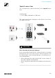

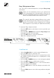
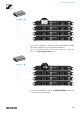
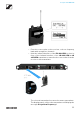
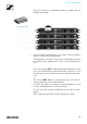

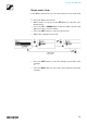
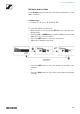
Table Of Contents
- Product information
- Products of the 2000 IEM series
- Accessories
- The frequency bank system
- Installing 2000 IEM series devices
- Installing the EK 2000 IEM
- Installing SR 2000 IEM / SR 2050 IEM
- Connectors on the rear of the device
- 1 3-pin mains socket
- 2 Cable grip for power supply DC cable (see Connecting/disconnecting the SR 2000 IEM / SR 2050 IEM with/from the power supply).
- 3 ¼" (6.3 mm) jack socket LOOP OUT BAL L(I)
- 4 ¼" (6.3 mm) jack socket LOOP OUT BAL R(II)
- 5 ¼" (6.3 mm) jack/XLR-3 combo socket BAL AF IN L(I)
- 6 ¼" (6.3 mm) jack/XLR-3 combo socket BAL AF IN R(II)
- 7 LED (yellow) for network activity indication
- 8 LAN socket (ETHERNET RJ 45)
- 9 BNC socket RF OUT
- Connecting/disconnecting the SR 2000 IEM / SR 2050 IEM with/from the power supply
- Creating a data network
- Connecting audio signals
- Daisy chaining audio signals
- Connecting antennas
- Mounting the transmitter into a rack
- Connectors on the rear of the device
- Installing the AC 3200-II
- Using 2000 IEM series devices
- Using the EK 2000 IEM
- Operating elements of the EK 2000 IEM diversity receiver
- Switching the EK 2000 IEM
- Lock-off function
- Displays on the EK 2000 IEM display panel
- Buttons for navigating through the menu
- Home Screen
- Setting options in the menu
- Menu structure
- Squelch menu item
- Easy Setup menu item
- Frequency Preset menu item
- Name menu item
- Balance menu item
- Mode menu item
- High Boost menu item
- Auto Lock menu item
- Advanced menu item
- Advanced -> Tune menu item
- Advanced -> Pilot Tone menu item
- Advanced -> Limiter menu item
- Advanced -> Volume Boost menu item
- Advanced -> LCD Contrast menu item
- Advanced -> Engineer Mode menu item
- Advanced -> Reset menu item
- Advanced -> Software Revision menu item
- Using the SR 2000 IEM / SR 2050 IEM
- Operating elements of the transmitters SR 2000 IEM / SR 2050 IEM
- Switching the SR 2000 IEM / SR 2050 IEM on and off
- Using the headphone output
- Configuring the audio channels (mono/stereo)
- Deactivating the RF signal (RF mute)
- Lock-off function
- Displays on the SR 2000 IEM / SR 2050 IEM display panel
- Buttons for navigating the SR 2000 IEM / SR 2050 IEM menu
- Setting options in the menu
- Sensitivity menu item
- Mode menu item
- Easy Setup menu item
- Frequency Preset menu item
- Name menu item
- Auto Lock menu item
- Advanced menu item
- Advanced > Tune menu item
- Advanced > Sync Settings menu item
- Advanced > RF Power menu item
- Advanced > Fullscreen Warnings menu item
- Advanced > LCD Contrast menu item
- Advanced > Reset menu item
- Advanced > IP Address menu item
- Advanced > Software Revision menu item
- Establishing a radio link
- Synchronizing devices
- Using the AC 3200-II
- Overview
- Product variants
- Frequency tables
- Specifications
- Pin assignment
- Cleaning and maintenance
- NOTICE

Using the EK 2000 IEM
55
▷ From the scan results on the receiver, select a frequency
bank with enough free channels.
▷ Hold the infrared interface of the EK 2000 IEM receiver in
front of the infrared interface of an SR 2000 IEM or SR
2050 IEM transmitter to transfer the scan results from the
receiver to this transmitter.
The selected transmitter becomes the master transmitter.
The display panels of the other transmitters will display the
message Assign New Frequency?