
Users Manual


Specifications
46
max. 0.4 A
with receiver switched on: max. 20 W (50 VA)
with receiver switched off, booster supply voltage switched on: max. 9.5 W
with receiver and booster supply voltage switched off: max. 4 W
3-pin, protection class I, as per IEC/EN 60320-1
436 x 215 x 44 (without rack mount “ears”)
approx. 4080 g (incl. rack mount “ears”)
approx. 3600 g (without rack mount “ears”)
12 V DC via antenna socket
max. 200 mA each, short-circuit proof, switchable
IEEE 802.3-2002, shielded RJ 45 socket with optional locking facility
AES3-2003, XLR-3, 44.1, 48, 88.2 or 96 kHz SR, 24 bits,
externally synchronizable
2 BNC sockets (75 Ω), daisy chain output
44.1 kHz, 48 kHz, 88.2 kHz, 96 kHz
75 Ω, transformer balanced, AC-coupled
input voltage range 200 mV … 5 Vpp
max. input voltage 15 V (DC + AC)
75 Ω, transformer balanced, AC-coupled
output voltage 2.5 V± 250 mV at 75 Ω source impedance
–10°C to +55°C
max. 85% at 40°C (non condensing)
100 to 240 V~, 50/60 Hz
the product must not be exposed to dripping and splashing (IP 20)
–25°C to +70°C
max. 90% at 40°C
the product must not be exposed to dripping and splashing (IP 20)
shock test according to IEC 68 or EN 60068, T2-27
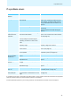
Overall device
Current consumption
Power consumptio
n
Mains connector
Dimensions W x D x H [mm]
Weight
Booster supply
Ethernet
Digital out
put
Word
clock connection
Accepted sampling rates
Word clock input
Word clock output
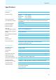
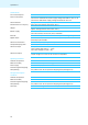
Operating conditions
Ambient temperature
Relative humidity
Power supply
Protection against dripping
and splashing
Storage and transport
conditions
Ambient temperature
Relative humidity
Protection against dripping
and splashing
Shock test