
Instruction manual - Digital 6000 (v4.0)


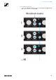
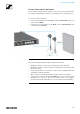
Table Of Contents
- The Digital 6000 Series
- Products in the Digital 6000 series
- Accessories
- Installing Digital 6000 series devices
- Installing the EM 6000
- Connectors on the rear of the device
- Connecting/disconnecting the EM 6000 to/from the power supply system
- Connecting the EM 6000 to a network
- Outputting analog audio signals
- Outputting digital audio signals
- Outputting audio via a Dante™ network (EM 6000 DANTE only)
- Connecting the word clock
- Connecting remote antennas
- Connecting rod antennas
- Installing the EM 6000 in a rack
- Installing the SKM 6000
- Installing the SK 6000
- Installing the SK 6212
- Installing the L 6000 | LM 6060 | LM 6061 | LM 6062
- Using Digital 6000 series devices
- Using the EM 6000
- Operating elements on the front of the device
- Switching the EM 6000 on and off
- Displays on the EM 6000 display panel
- Buttons for navigating through the menu
- Home screen
- Muting the audio signal
- Setting options in the menu
- Menu structure
- Frequency menu item
- Name menu item
- Sync Settings menu item
- Encryption menu item
- Command Mode menu item
- Scan & Auto-Setup menu item
- Walktest menu item
- AF Output menu item
- Test Tone menu item
- Bank Edit menu item
- System menu item
- System -> Transmission Mode menu item
- System -> Wordclock menu item
- System -> Network menu item
- System -> Device ID menu item
- System -> Dante Settings (only EM 6000 DANTE) menu item
- System -> Booster Feed menu item
- System -> Brightness menu item
- System -> Auto Setup menu item
- System -> Info menu item
- System -> Hardware menu item
- System -> Help menu item
- System -> TX Update menu item
- System -> Reset menu item
- Using the headphone output
- Updating the firmware of the receiver
- Updating the firmware of the Dante™ interface
- Status messages
- Using the SKM 6000
- Using the SK 6000
- Using the SK 6212
- Using the L 6000
- Switching the L 6000 on and off
- Charging rechargeable batteries
- Meaning of the LEDs on the L 6000 charger and LM 6060, LM 6061 and LM 6062 charging modules
- Preparing rechargeable batteries for storage (storage mode)
- Resetting settings (factory reset)
- Updating the firmware
- Operating the L 6000 via a network
- Establishing a radio link
- Synchronizing devices
- Overview
- Recommendations for using antennas
- Equidistant frequency grid
- Link Density mode
- Word clock scenarios for digital audio (AES3 and Dante™)
- Overview
- Product variants
- Specifications
- Cleaning and maintenance

Installing the EM 6000
30
Installing the EM 6000
These sections contain detailed information about installing the EM 6000.
You can find information about operating the EM 6000 under „Using the
EM 6000“.
Connectors on the rear of the device
Product overview for the rear side of the EM 6000
►
1 Power socket
• See „Connecting/disconnecting the EM 6000 to/from the power
supply system“
2 Ethernet socket for controlling the device via the network and Sennhe-
iser WSM
• See „Connecting the EM 6000 to a network“
3 Digital Audio AES 3 digital audio output
• See „Outputting digital audio signals“
4 Word clock BNC sockets
• See „Connecting the word clock“
5 Bal AF out analog audio outputs for the CH 1 and CH 2 channels
• One XLR and 6.3 mm (1/4") jack per channel, transformer-balanced,
parallel
• See „Outputting analog audio signals“
6 BNC antenna inputs and BNC antenna outputs for cascading
• See „Connecting remote antennas“
• See „Connecting rod antennas“
• See „Recommendations for using antennas“