
Instruction manual ew D1


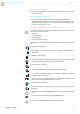

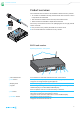
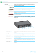
Table Of Contents
- Contents
- Important safety instructions
- Optimum sound the easy way
- Package contents
- Product overviews
- Putting the products into operation
- Avoiding sources of interference
- Direct line of sight recommended
- Putting the receiver into operation
- Fitting the device feet
- Mounting the rack mount “ears”
- Connecting the rod antennas to the receiver
- Mounting the receiver into a 19" rack
- Mounting a single receiver into a rack
- Mounting the rod antennas to the front of the rack
- Mounting two receivers into a rack
- Connecting the receiver to a mixing console
- Connecting receivers in a network
- Connecting the receiver to the power supply system
- Putting the bodypack transmitter into operation
- Preparing the headset microphone for use
- Attaching the clip-on microphone to clothing
- Putting the handheld transmitter into operation
- Recharging the accupack
- Using the products
- Switching the devices on or off
- Checking the charge status of the batteries or accupacks
- Checking the RF signal level
- Muting the bodypack transmitter or the SKM-S D1 handheld transmitter
- Pairing a receiver with a transmitter
- Identifying paired devices
- Using the devices in multi-channel operation
- Switching between the standard display and the extended standard display
- Using the operating menu of the receiver
- Using the buttons for navigation
- Overview of the operating menu of the receiver
- Changing the name of the radio link
- Activating/deactivating the low-cut filter
- Adjusting the equalizer
- Adjusting the de-esser
- Activating/deactivating the dynamic compression
- Resetting the audio settings
- Coarsely adjusting the output level of the receiver (Mic/Line)
- Fine-tuning the output level of the receiver
- Activating/deactivating the lock mode
- Activating/deactivating the MUTE switch of the transmitter
- Adjusting the display brightness
- Calling up help functions
- Retrieving system information
- Resetting the receiver to the factory default settings
- Changing the network configuration
- Displaying the IPv6 address
- Displaying the MAC address
- Performing a walk test (checking the reception quality)
- Controlling, monitoring or updating devices via the network
- Cleaning and maintaining the products
- If a problem occurs ...
- Specifications
- Accessories
- Manufacturer Declarations

8
Product overviews
Operating elements – rear panel
7 Status LED
lights up green:
A radio link to the transmitter is established. The batteries of the received
transmitter are sufficiently charged.
flashes green:
The PAIR button has been short-pressed. Paired devices are being identified.
flashes alternately
green and red:
The PAIR button has been long-pressed. The receiver establishes a radio link
to a transmitter whose PAIR button has also been long-pressed.
lights up yellow:
The received transmitter has been muted with the MUTE switch. In addition,
Muted is displayed on the display panel.
flashes red:
The battery capacity of the received transmitter is only sufficient for approx.
30 minutes of operation.
lights up red:
No radio link to a transmitter. In addition, the background of the display panel
changes back and forth between light and dark and No Link appears on the
display panel.
8
9
0
A
B
C
D
8 R-SMA socket ANT II Antenna input II for connecting a supplied 2G4 rod antenna (for details, see
page 16)
9 Cable grip for the cable of the power supply unit
0 DC IN socket for connection of the power supply unit
A ¼" (6.3 mm) jack socket
AF OUT UNBAL
Unbalanced audio output for connection to the ¼" (6.3 mm) jack input of the
mixing console (for details, see page 20)
B XLR-3 socket AF OUT BAL Balanced audio output for connection to the XLR-3 input of the mixing console
(for details, see page 20)
C Ethernet socket LAN for connecting to a network router or a switch (e.g. to control, monitor and
update several receivers via a mobile device or a computer (for details, see
page 20)
D R-SMA socket ANT I Antenna input I for connecting a supplied 2G4 rod antenna (for details, see
page 16)