
User Manual

Installing the EM 100 G4
22
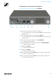
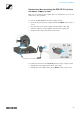
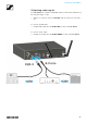
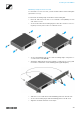
Connectors on the rear of the device
Product overview for the rear side of the EM 100 G4
►
1 Strain relief for the cable of the power supply unit
• See “Connecting/disconnecting the EM 100 G4 to/from the power
supply system”
2 Connecting cables for the power supply unit (DC IN)
• See “Connecting/disconnecting the EM 100 G4 to/from the power
supply system”
3 XLR-3 socket for audio output, balanced (AF OUT BAL)
• See “Outputting audio signals”
4 6.3 mm jack socket for audio output, unbalanced (AF OUT UNBAL)
• See “Outputting audio signals”
5 RJ-10 interface (DATA)
• See “Creating a data network”
6 RJ-10 interface (DATA)
• See “Creating a data network”
7 BNC socket, antenna input II (ANT II) with remote power supply unit
• See “Connecting antennas”
8 BNC socket, antenna input I (ANT I) with remote power supply unit
• See “Connecting antennas”