
Instruction manual ew 100 G4
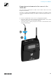
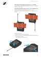
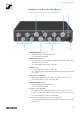
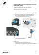
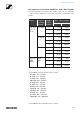
Table Of Contents
- Overview
- ew 100 G4 series products
- Accessories
- The frequency bank system
- Installing and starting up ew 100 G4 series devices
- Installing the EM 100 G4
- Installing the SKM 100 G4
- Installing the SK 100 G4
- Installing the ASA 214
- Using ew 100 G4 series devices
- Using the EM 100 G4
- Operating elements on the front of the device
- Switching the EM 100 G4 on and off
- Muting the audio output
- Lock-off function
- Displays on the EM 100 G4 display panel
- Buttons for navigating through the menu
- Home screen
- Setting options in the menu
- Menu structure
- Squelch menu item
- Easy Setup menu item
- Frequency Preset menu item
- Name menu item
- AF Out menu item
- Equalizer menu item
- Auto Lock menu item
- Advanced menu item
- Advanced -> Tune menu item
- Advanced -> Guitar Tuner menu item
- Advanced -> Pilot Tone menu item
- Advanced -> LCD Contrast menu item
- Advanced -> Reset menu item
- Advanced -> Software Revision menu item
- Using the SKM 100 G4
- Operating elements of the SKM 100 G4 handheld transmitter
- Switching the SKM 100 G4 handheld transmitter on and off
- Muting the handheld transmitter (AF mute)
- Deactivating the RF signal (RF mute)
- Lock-off function
- Displays on the SKM 100 G4 handheld transmitter display panel
- Buttons for navigating the SKM 100 G4 menu
- Setting options in the menu
- Sensitivity menu item
- Frequency Preset menu item
- Name menu item
- Auto Lock menu item
- Advanced menu item
- Advanced > Tune menu item
- Advanced > Mute Mode menu item (SKM 100 G4-S only)
- Advanced > Pilot Tone menu item
- Advanced > LCD Contrast menu item
- Advanced > Reset menu item
- Advanced > Software Revision menu item
- Using the SK 100 G4
- Operating elements of the SK 100 G4 bodypack transmitter
- Switching the SK 100 G4 bodypack transmitter on and off
- Muting the bodypack transmitter (AF mute)
- Deactivating the RF signal (RF mute)
- Lock-off function
- Displays on the SK 100 G4 bodypack transmitter display panel
- Buttons for navigating the SK 100 G4 menu
- Setting options in the menu
- Sensitivity menu item
- Frequency Preset menu item
- Name menu item
- Auto Lock menu item
- Advanced menu item
- Advanced > Tune menu item
- Advanced > Mute Mode menu item
- Advanced > Cable Emulation menu item
- Advanced > Pilot Tone menu item
- Advanced > LCD Contrast menu item
- Advanced > Reset menu item
- Advanced > Software Revision menu item
- Establishing a radio link
- Synchronizing devices
- Using the ASA 214
- Overview
- Product variants
- Frequency tables
- Specifications
- Pin assignment
- Cleaning and maintenance

Installing the ASA 214
43
Connectors on the rear of the device
Product overview for the rear side of the ASA 214
►
1 ANT RF IN B BNC socket
• Antenna input of diversity branch B
• See “Connecting antennas”
2 RF OUT A BNC socket
• RF output only for connecting an additional ASA 214 to build an 8-
channel diversity system
• See “Configuring multi-channel systems”
3 DC INsocket
• To connect the NT 1-1 power supply unit
• See “Connecting/disconnecting the ASA 214 to/from the power sup-
ply system”
4 4 BNC sockets B1 to B4
• RF outputs of diversity branch B for connection to the receiver
• See “Connecting receivers to the ASA 214”
5 ANT RF IN A BNC socket
• Antenna input of diversity branch A
• See “Connecting antennas”
6 4 BNC sockets A1 to A4
• RF outputs of diversity branch A for connection to the receiver
• Every one of these RF outputs can also provide voltage to a receiver.
• See “Connecting receivers to the ASA 214”
7 Strain relief for the cable of the power supply unit
• See “Connecting/disconnecting the ASA 214 to/from the power sup-
ply system”