
Instruction manual 300 IEM Series G3 Download300 IEM Series: SR 300 IEM G3 and EK 300 IEM G3
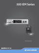
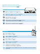
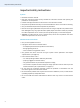
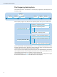
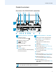
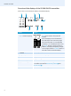
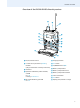
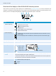
Table Of Contents
- Important safety instructions
- The evolution wireless series ew 300 IEM G3
- The frequency bank system
- Product overviews
- Putting the devices into operation
- Putting the SR 300 IEM G3 transmitter into operation
- Setting up the transmitter on a flat surface
- Mounting the transmitter into a 19” rack
- Connecting the mains unit
- Connecting devices to the input sockets
- Connecting devices to the output sockets
- Connecting a remote antenna to the BNC socket and positioning the antenna
- Connecting the AC 3 antenna combiner to the BNC socket
- Daisy chaining audio signals
- Connecting transmitters in a network
- Putting the EK 300 IEM G3 diversity receiver into operation
- Putting the SR 300 IEM G3 transmitter into operation
- Using the devices
- Switching the devices on/off
- Monitoring the audio signal via headphones
- Deactivating the lock mode temporarily
- Selecting a standard display on the diversity receiver
- Adjusting the audio channels on the transmitter
- Activating/deactivating the RF signal on the transmitter
- Synchronizing transmitters and EK 300 IEM G3 receivers via the infra-red interface
- Using the operating menus
- Synchronizing the transmitter with the diversity receiver
- Cleaning the devices
- If a problem occurs ...
- Specifications
- Manufacturer Declarations

Product overviews
5
Product overviews
Overview of the SR 300 IEM G3 transmitter
A
B
PUSH
PUSH
L(I)
R(II)
+22dBu
MAX
Loop Out
BAL
L(I)
+Mono
R(II)
BAL
AF IN
+22dBu MAX
RF OUT
FREQ Range-D 780-822 MHz
DESIGNED AND MADE IN GERMANY
Stereo Transmitter SR 300 IEM
IDENT NO 627925
SER NO 2518100155
IC 2099A-G3SREK
ANT
531.375
ew300IEM
B.Ch: 20.24
Standard -18dB
MHz
Stereo Transmitter
PEAK
0
-20
-30
-40
AF I
PEAK
-10
0
-20
-30
-40
AF II
AF II
-10
Operating elements – front panel Operating elements – rear panel
Headphone output,
¼” (6.3 mm) jack socket ( )
Headphone volume control
button, backlit
Infra-red interface
Display panel, backlit in orange
Jog dial
STANDBY button
operation indication (red backlighting),
ESC function (cancel)
Cable grip for power supply DC cable
DC socket (DC IN) for connection of
NT 2-3 mains unit
LED (yellow) for network activity
indication
LAN socket (ETHERNET RJ 45)
Audio output left (LOOP OUT BAL L(I)),
¼” (6.3 mm) jack socket
Audio output right (LOOP OUT BAL R(II)),
¼” (6.3 mm) jack socket
Type plate
Audio input left (BAL AF IN L(I)+Mono),
¼” (6.3 mm) jack/XLR-3 combo socket
Audio input right (BAL AF IN R(II)),
¼” (6.3 mm) jack/XLR-3 combo socket
Antenna output (RF OUT)
with remote power supply input (DC IN),
BNC socket
In mono mode, the signal from the left audio input BAL AF IN L(I)+Mono
(¼” (6.3
mm) jack/XLR-3 combo socket) is transmitted.
A
B