
Instruction manual ew 300-500 G4


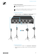


Installing the ASA 214
60
Connectors on the rear of the device
Product overview for the rear side of the ASA 214
►
1 ANT RF IN B BNC socket
• Antenna input of diversity branch B
• See “Connecting antennas”
2 RF OUT A BNC socket
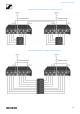
• RF output only for connecting an additional ASA 214 to build an 8-
channel diversity system
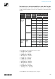
• See “Configuring multi-channel systems”
3 DC INsocket
• To connect the NT 1-1 power supply unit
• See “Connecting/disconnecting the ASA 214 to/from the power sup-
ply system”
4 4 BNC sockets B1 to B4
• RF outputs of diversity branch B for connection to the receiver
• See “Connecting receivers to the ASA 214”
5 ANT RF IN A BNC socket
• Antenna input of diversity branch A
• See “Connecting antennas”
6 4 BNC sockets A1 to A4
• RF outputs of diversity branch A for connection to the receiver
• Every one of these RF outputs can also provide voltage to a receiver.
• See “Connecting receivers to the ASA 214”
7 Strain relief for the cable of the power supply unit
• See “Connecting/disconnecting the ASA 214 to/from the power sup-
ply system”