
User Manual
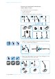
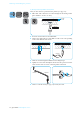
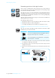
Table Of Contents
- Important safety information
- Sennheiser SpeechLine – True to the word
- Overview of the SpeechLine IS microphone series
- Package contents
- Product overview
- Overview of the MEB 114 (-S) boundary layer microphones
- Overview of the MEB 102 (-L) | MEB 104 (-L) surface-mounted boundary layer microphones
- Overview of the MEG 14-40 (-L(-II)) gooseneck microphones
- Overview of the MZH 30xx (-L) goosenecks
- Overview of the MAT 133 (-S) | MAT 153-S table stands
- Overview of the MAS 133 inline switch box
- Overview of the MAS 1 microphone button
- Overview of the MZFS 60 | MZFS 80 microphone stands
- Mounting and installing the products
- Connecting the products
- Adjusting and using the products
- Cleaning and maintaining the products
- Specifications
- Manufacturer Declarations

Connecting the products
SpeechLine IS microphone series | 29
B) Connecting microphones to a
DSP with logic function
To establish a logic connection in addition to the audio connection:
왘 Use a 3-wire cable (Ø 0.14–0.5 mm
2
) to connect the microphone or the
table stand to a GPIO port or logic port of the DSP.
왘 Lay all cables in such a way that other pe
rsons cannot trip over them
and injure themselves.
왘 Observe the connection inst
ructions in the instruction manual of your
DSP.
왘 Set the slide switch for setting the behavior of the microphone button
to ON in order to activate the “DSP remote mode”.
I
n “DSP remote mode”, the microphone is permanently on and is muted
or activated via the DSP. The microphone thus permanently provides a
reference signal for AEC algorithms in the DSP.
DSP
logic
Logic in
Ground
Logic out
MAT 133-S MAT 153-SMEB 114-S
ON PTM PTT ON
OFF
MAT 133-S
MAT 153-S
MEB 114-S