freeport_514013_0808_Sp5.book Seite 1 Mittwoch, 26.
freeport_514013_0808_Sp5.book Seite 1 Mittwoch, 26. November 2008 2:16 14 Contents Important safety instructions ......................................................... 2 The freePORT systems ...................................................................... 3 Delivery includes .......................................................................... 4 EM 1 receiver ...................................................................................... 4 SK 2 bodypack transmitter ....................
freeport_514013_0808_Sp5.book Seite 2 Mittwoch, 26. November 2008 2:16 14 Important safety instructions y Read this instruction manual. y Keep this instruction manual in a safe place. Always include this y y y y y y y y y y y 2 instruction manual when passing the device and the mains unit on to third parties. Heed all warnings and follow all instructions. Clean the device and the mains unit only with a dry cloth. Refer all servicing to qualified service personnel.
freeport_514013_0808_Sp5.book Seite 3 Mittwoch, 26. November 2008 2:16 14 The freePORT systems Designed for different areas of application, the freePORT systems are available in three variants. y Presentation Set: This system is ideal for presentation applications. The unobtrusive ME 2 clip-on microphone is virtually invisible. y Instrument Set: This system is for connecting musical instruments (e.g. guitar) which have a ¼” (6.3 mm) jack socket directly to the bodypack transmitter.
freeport_514013_0808_Sp5.book Seite 4 Mittwoch, 26. November 2008 2:16 14 Instructions for use X ¼” (6.
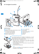
freeport_514013_0808_Sp5.book Seite 5 Mittwoch, 26. November 2008 2:16 14 Connecting the receiver 왘 Insert the DC connector on the mains cable into the DC socket and connect it to the mains. The green LED for operation indication (POWER) lights up and the receiver is ready for operation. 왘 To deactivate the receiver, remove the mains plug from the mains outlet. Aligning the antennas 왘 Set up the antennas and align them upwards in a V-shape. The LEDs A and B indicate which diversity section (i.e.
freeport_514013_0808_Sp5.book Seite 6 Mittwoch, 26. November 2008 2:16 14 SK 2 bodypack transmitter Operating controls ON/OFF button Operation and battery status indication, red LED 쐋 Microphone/instrument input, 3.
freeport_514013_0808_Sp5.book Seite 7 Mittwoch, 26. November 2008 2:16 14 Connecting the microphone/instrument cable The audio input is designed for the connection of both the ME 2 clip-on microphone and instruments (e.g. guitars). 왘 Connect the 3.5 mm jack plug from the microphone/instrument cable to the 3.5 mm jack socket 쐋. 왘 Check the setting of the MIC/INST slide switch which allows you to switch between microphone and instrument operation. If necessary, readjust the setting.
freeport_514013_0808_Sp5.book Seite 8 Mittwoch, 26. November 2008 2:16 14 SKM 3 radio microphone Operating control Sound inlet basket Locking ring of battery compartment 쐋 Body of radio microphone Battery compartment (not visible from outside) Antenna (can be screwed off) Operation and battery status indication, red LED (POWER) ON/OFF switch Channel selector switch CH (1 to 4) Type plate Serial number Note: The microphone head of the radio microphone cannot be changed.
freeport_514013_0808_Sp5.book Seite 9 Mittwoch, 26. November 2008 2:16 14 Switching the radio microphone on/off 왘 Use the ON/OFF switch to switch the radio microphone on or off. If the radio microphone is switched on, the red LED lights up. Note: Remove the battery when the transmitter will not be used for extended periods of time. Selecting and changing a channel 왘 Switch off the radio microphone. 왘 Open the radio microphone (“Inserting/replacing the battery”).
freeport_514013_0808_Sp5.book Seite 10 Mittwoch, 26. November 2008 2:16 14 Adjusting the squelch threshold Interference due to other transmission links can be eliminated as follows: 왘 Switch off the transmitter. The receiver should no longer receive a signal. 왘 If the receiver still receives a signal, use the SQUELCH control to increase the squelch threshold so that the signal will no longer be received.
freeport_514013_0808_Sp5.book Seite 11 Mittwoch, 26. November 2008 2:16 14 If problems occur...
freeport_514013_0808_Sp5.book Seite 12 Mittwoch, 26. November 2008 2:16 14 Specifications of the freePORT systems System characteristics Transmission/receiving frequencies 4 UHF transmission/receiving frequencies Range A: 719 to 721 MHz (719.15 – 719.75 – 720.15 – 720.85 MHz) Range B: 691 to 693 MHz (691.00 – 691.40 – 692.35 – 692.90 MHz) Range C : Switching bandwidth Signal-to-noise ratio THD (1 kHz) Temperature range 742.5 to 744.5 MHz (742.65 – 743.35 – 743.85 – 744.45 MHz) 863 to 865 MHz (863.
freeport_514013_0808_Sp5.book Seite 13 Mittwoch, 26.
freeport_514013_0808_Sp5.book Seite 14 Mittwoch, 26. November 2008 2:16 14 Manufacturer declarations Warranty Sennheiser electronic GmbH & Co. KG gives a warranty of 24 months on this product. For the current warranty conditions, please visit our web site at www.sennheiser.com or contact your Sennheiser partner. CE Declaration of Conformity 0682 This equipment is in compliance with the essential requirements and other relevant provisions of Directives 1999/ 5/EC, 2004/108/EC or 2006/95/EC.
freeport_514013_0808_Sp5.book Seite 16 Mittwoch, 26. November 2008 2:16 14 Sennheiser electronic GmbH & Co. KG Am Labor 1 30900 Wedemark, Germany www.sennheiser.com Printed in Taiwan Publ.