
Instruction manual guidePORT 3200 system


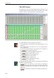


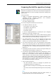
Table Of Contents
- 1 Contents
- 2 Safety Information
- General safety information
- Safety information on the equipment
- Units with rechargeable batteries
- Units with mains connection
- Units with cables and connected accessories
- Units requiring permanent installation
- Units operated on standard or rechargeable batteries
- Units with headphone connection
- Units generating high-frequency alternating electromagnetic fields
- Statements regarding FCC and industry Canada
- Safety for your computer files
- 3 Getting to know the System
- 4 Basics of the Components
- Overview of the components and structures of the system
- The function of the components
- 5 Putting the Components into Operation
- Cell transmitters
- Putting the cell transmitters into operation
- Unpacking the units
- Where to place the cell transmitters
- Fixing the cell transmitter feet
- Mounting the cell transmitters into a rack
- Connecting the mains cable
- Connecting the headphones
- Connecting sound sources for Live Events
- Connecting cell transmitters to a laptop or Base Station PC
- Networking several cell transmitters
- Turning the cell transmitters on/off
- Operating the cell transmitters
- The buttons on the cell transmitter
- The display of the cell transmitter
- The status display of the cell transmitter
- Selecting a menu item
- Displaying the installation parameters
- Changing the volume of the headphone output
- Selecting an audio source to listen to via the headphone output
- Damping excessively loud audio signals
- Temporarily changing antenna parameters for test purposes
- Displaying the firmware version
- Changing the display contrast
- Carrying out a reset
- Restoring the factory settings on the cell transmitter
- Troubleshooting
- Structure of the cell transmitter’s menu
- Putting the cell transmitters into operation
- Portable transmitters
- Antenna
- Identifiers
- Receivers
- Putting the receivers into operation
- Changing the receiver settings
- Operating the receivers
- Turning the receivers on/off
- Selecting the category (16-key receiver only)
- Setting the volume
- Calling up information at an exhibit
- Repeating Storage Events
- Stopping sound reproduction
- Calling up the Help function (only if the key is available)
- Calling up detailed information (only if the key is available)
- Possible operating states indicated by the red and the green LED
- Chargers
- Cell transmitters
- 6 Project planning
- Before you start
- Frequency planning
- Example 1: A small gallery
- Planning the content
- General overview of the structure of a project
- How many locations do you need?
- Providing a location plan of the exhibits
- Planning the number of categories
- Recording informational texts and setting the audio quality
- Collecting and structuring all Storage Events
- Collecting and structuring all Live Events
- How many cells do you need?
- Technical planning
- Planning the content
- Example 2: A town with several large-scale exhibitions
- Planning the content
- General overview of the structure of a project
- How many locations do you need?
- For which Events is the location “0” suitable? For which Events are the other locations suitable?
- How high should the start ID of the fixed Events be?
- Providing a location plan of the exhibits
- Planning the number of categories
- Creating a list of all Storage Events
- Recording informational texts and setting the audio quality
- Collecting and structuring all Storage Events
- Collecting and structuring all Live Events
- How many cells do you need?
- Calculating the number of segments for stationary download in advance
- Planning guided tours
- Technical planning
- Planning the content
- Overview of all Events types
- The principal restrictions
- Further example configurations
- 7 Basics of the Software
- Possible hardware versions
- System requirements
- The software modules
- The folder structure
- Overview of the folder structure
- Contents of the folders
- Software folder
- Software file folder “bin”
- Communication folder “sys”
- The installation folder “GPInstallations”
- The folders with the name of a location
- The folder of compressed audio files (GPP Audio)
- The folder of compressed Intro files (Intro)
- The folder with cell transmitter files (System)
- The folder of the audio “wave” files (WAV-Audio)
- The folder of announcements (Announcements)
- The system files
- Using the software
- Re-installing, repairing or de-installing software modules
- 8 The Installation Manager (INM)
- General procedure
- The INM screen
- Starting the INM
- Setting up a default project
- Configuring the project (detailed description)
- Configuring a location
- The “Location configuration” dialog box
- Changing the sorting of the table cells
- Editing tables
- Editing categories
- Configuring cell transmitters/MTS
- Adding or replacing cell transmitters/MTS
- Reassigning MTS
- Removing an MTS
- Changing the loader value of an MTS
- Entering or changing the site of the cell transmitter
- Selecting the RF channel
- Setting the transmitting power
- Turning the RF output on and off
- Selecting the antenna type
- Entering or changing the site of the antenna
- Creating cells
- Configuring Events
- Adding a new Event
- Deleting an Event
- Restoring a deleted or deactivated Event
- Renaming an Event
- Changing the Event features
- Configuring special Events
- Assigning an audio source to an Event
- Changing the audio source of an Event
- Deleting the audio source of an Event
- Assigning an MTS for a category to an Event
- Deleting an assignment to an MTS
- Linking the audio information of an Event from one category to another category
- Setting up the identifiers
- Adding identifiers to the identifier table
- Deleting identifiers
- Changing the identifier default settings
- Reproducing Storage Events
- Assigning the correct location to an Event
- Checking the configuration of a location
- Printing the configuration data of a location as an HTML document
- Accepting/discarding the configuration of a location
- Adding locations
- Deleting locations
- Configuring jobs
- Transferring identifier configurations to the PDA
- Changing options
- Monitoring the INM
- Day-to-day operation (Operator mode)
- The “Dongle Info” dialog box
- Recommendations/Tips
- 9 The Base Station Manager (BSM)
- Before you start
- General procedure
- The BSM screen
- The “Update” window
- The “Status” window
- Removing the contents of the “Status” or “Update” window
- Monitoring USB activity
- Searching for connected cell transmitters
- Displaying status information of the cell transmitters
- Monitoring the cell transmitter statuses
- Updating the cell transmitter status display
- Selecting the cell transmitter status options
- Opening the “Service Dialog” window
- Checking the connected antennas
- Resetting the connected cell transmitters
- Updating the cell transmitter firmware
- Quitting the BSM
- 10 The Charger Manager (CHM)
- Before you start
- General procedure
- The CHM screen
- Preparing the CHM for operation (Setup)
- Operating the CHM in “Standard Operation” mode
- Operating the CHM in “Installation Administration” mode
- Changing between “Standard Operation” and “Installation Administration” mode
- Changing the receiver presets permanently
- Displaying the receiver presets (Get Settings)
- Displaying the version numbers of the internal receiver software and hardware
- Reading out statistical data manually
- Preparing stationary download
- Deleting the Storage Events audio data
- Setting the country code for portable transmitters
- Displaying the country code of the portable transmitters (Get Settings)
- 12 The Identifier Control (IDC)
- Before you start
- General procedure
- The screen
- The menus of the PDA software
- The “File” menu
- The “Cell” menu
- The “Event” menu
- The “Identifier” menu
- Reading the current identifier data (Read Parameters)
- Transmitting identifier settings from the PDA to an identifier (Send Parameters)
- Checking the internal clock of an identifier (Read Time)
- Setting the internal clock of an identifier (Set Time)
- Setting an identifier to standby mode (Standby on)
- Setting an identifier to normal operation (Standby off)
- Transmitting System Events from the PDA to identifiers
- Triggering the switching over of the category (“Cat” System Event )
- Triggering the download of the variable Events of a location (“Location entrance” System Event )
- Turning the alarm on/off (“Alarm On” and “Alarm Off” System Events)
- Setting up the automatic return to the RF channel of the portable transmitter (System Event 97)
- 13 The Statistics Manager (STM)
- Before you start
- General procedure
- The STM screen
- The STM menus
- The “File” menu
- The “Edit” menu
- Editing the defaults
- Establishing the connection to the SMC modules on the Charger PCs
- Changing the default TCP/IP port of an SMC module
- Setting up jobs
- Selecting the type of job
- Selecting the period to be taken into account in the job
- Selecting the defaults for the job
- Saving the job
- Deleting a job
- Changing a job
- The “Collectors” menu
- The “View” menu
- The “Help” menu
- 14 The Announcement Manager (ANM)
- Before you start
- General Procedure
- Preparing location “0” for announcements
- The ANM screen
- Starting the ANM
- Configuring the ANM (Administrator mode)
- Monitoring the ANM
- Day-to-day operation (Operator mode)
- 15 The Visitor Profiler (VPR)
- 16 The License Manager Server (LMS)
- 17 Maintenance and Care
- 18 Specifications
- 19 Glossary

Before you start
10-2
Before you start
The CHM software allows you to monitor the connected chargers and to
program the receivers inserted into the chargers.
Before you can work with the CHM software:
! The CHM requires operational RS 485 ports. These can be the ports of
an RS 485 card built in the computer or made available via an RS 232-
to-RS 485 interface converter.
Note:
If possible, use an RS 485 card (or an RS 232-to-RS 485 interface
converter) recommended by Sennheiser for connecting the chargers
to the Charger PC (see “Recommendations concerning the RS 485
interface” on page 5-46).
! The driver for the RS 485 ports must be installed and the Windows
Device Manager must recognize the RS 485 ports as being
“operational”!
! The chargers must be correctly connected to the serial RS 485
interfaces of the computer by means of suitable cables.
Note:
When using self-made cables for connecting the chargers to the
Charger PC, observe the correct wire assignment of the cables (please
contact your local Sennheiser dealer for assistance).
! A string (daisy-chain) with a maximum of 32 chargers can be
connected to each RS 485 interface. Each charger has ten charging
compartments (slots) for inserting the receivers. A maximum of 320
charging slots per string can thus be accessed.
! The CHM can manage a maximum of 16 strings (i.e. 5,120 receivers).
! The receivers must be inserted completely into the charging
compartments.