SR 2000 IEM SR 2050 IEM Instruction manual
Contents Contents Important safety instructions ............................................................................................................................................................. 2 The SR 2000 IEM and SR 2050 IEM transmitters ............................................................................................................................. 4 The frequency bank system ........................................................................................................
Important safety instructions Important safety instructions 1. Read these instructions. 2. Keep these instructions. Always include these instructions when passing the transmitter on to third parties. 3. Heed all warnings. 4. Follow all instructions. 5. Do not use this apparatus near water. 6. Clean only with a dry cloth. 7. Do not block any ventilation openings. Install in accordance with the manufacturer’s instructions. 8.
Important safety instructions This symbol is intended to alert the user to the risk of electric shock if the transmitter is opened. There are no user serviceable parts inside. Refer servicing to qualified personnel only. This symbol is intended to indicate the presence of important operating and maintenance instructions in the literature accompanying this transmitter. Overloading Do not overload wall outlets and extension cables as this may result in fire and electric shock.
The SR 2000 IEM and SR 2050 IEM transmitters The SR 2000 IEM and SR 2050 IEM transmitters With the SR 2000 IEM and SR 2050 IEM 2-channel/stereo monitoring transmitters, musicians, video and sound amateurs, reporters/broadcasters, etc. can directly monitor the received sound signals without troublesome cables or monitor speakers being required. In addition, the transmitters can also be used for any application where talkback signals are to be transmitted.
Delivery includes Each of the channels in the frequency banks “1” to “20” has been factory-preset to a fixed transmission frequency (frequency preset). The factory-preset frequencies within one frequency bank are intermodulation-free. These frequencies cannot be changed. For an overview of the frequency presets, please refer to the supplied frequency information sheet. Updated versions of the frequency information sheet can be downloaded from the corresponding product page on our website at www.sennheiser.
Product overview Product overview Overview of the SR 2000 IEM/SR 2050 IEM transmitter The SR 2050 IEM twin transmitter has the same operating elements as the SR 2000 IEM transmitter. All information contained in this instruction manual refers to both transmitters. SR 2050 IEM PEAK PEAK A 0 -10 -20 -30 -40 AF I 0 -10 -20 -30 -40 AF II B.Ch: 5.14 Stereo Transmitter SR 2050 IEM FREQ RANGE-Dw 790-865 mHz ART NO 627945 SER NO 251810043 100 - 240V 50/60Hz 0.
Product overview Overview of the displays After switch-on, the transmitter displays the standard display. PEAK PEAK 0 -10 -20 -30 -40 AF I 0 -10 -20 -30 -40 AF II 햴 B.Ch: 5.14 **2050** 552.
Putting the transmitter into operation Putting the transmitter into operation Setting up the transmitter on a flat surface Do not fit the device feet when mounting the transmitter into a 19" rack. 왘 Clean the base of the transmitter where you want to fix the device feet. 왘 Fit the device feet to the four corners of the transmitter. 왘 Place the transmitter on a flat, horizontal surface. Please note that the device feet can leave stains on delicate surfaces.
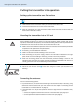
Putting the transmitter into operation Connecting and positioning a remote antenna Use a remote antenna when the transmitter position is not the best antenna position for optimum transmission. You can choose between two antennas (see “Accessories” on page 34): • A 2003 UHF passive directional broadband antenna • A 1031 passive omni-directional broadband antenna 왘 Use a low-attenuation 50-Ω cable to connect the antenna to the transmitter.
Putting the transmitter into operation • 2 BNC extension cables (screw-in BNC socket ' to BNC connector ' • 2 antenna holders ), , • 4 screws, • 2 washers 4 • 2 nuts , . 1 왘 Guide the BNC connector of the BNC extension cable through the hole in the rack mount “ear” . 왘 Connect the BNC connector to the antenna output . 왘 Screw the antenna holder to the BNC socket ' using the supplied washer ' nut and .
Putting the transmitter into operation 왘 Connect the rod antennas & to the two BNC sockets '. & ' Connecting an audio source to the input sockets Stereo Trans PUSH PUSH FREQ RANGE-Dw 790-865 mHz ART NO 503841 SER NO 2518100095 IC 2099A-SR20x0 DESIGNED AND MADE IN GERM ANT L(I) BAL AF IN + 22dBu MAX R(II) RF OUT 왘 Use a suitable cable to connect the output of the audio source (e.g. mixing console) to the ¼” (6.3 mm) jack/XLR-3 combo socket BAL AF IN L (I) and/or BAL AF IN R (II) .
Putting the transmitter into operation 왘 Connect the output socket LOOP OUT BAL R(II) of transmitter A to the input socket BAL AF IN R(II) of transmitter B. 왘 Connect the output socket LOOP OUT BAL R(II) of transmitter B to the input socket BAL AF IN R(II) of transmitter C. 왘 Repeat for the other transmitters. The AF output sockets LOOP OUT BAL L(I) and/or LOOP OUT BAL R(II) will work only when the transmitter is switched on and powered.
Using the transmitter 왘 Pass the mains cable through the cable grip . B 100 - 240V 50/60Hz 0.2 A ETHERNET RJ-45 왘 Connect the mains cable to the mains socket . 왘 Plug the mains plug into the wall socket. Using the transmitter To establish a transmission link, proceed as follows: 1. Switch the transmitter on (see next section). 2. Switch the EK 2000 IEM receiver on (see the instruction manual of the receiver). The transmission link is established.
Using the transmitter 왘 Press the jog dial. The transmission icon is displayed again. To switch the transmitter to standby mode: 왘 If necessary, deactivate the lock mode (see page 14) 왘 Keep the STANDBY button pressed until “OFF” appears on the display panel. The transmitter switches to standby mode. When in the operating menu, pressing the STANDBY button will cancel your entry (ESC function) and return you to the standard display.
Using the transmitter 왘 Press the jog dial. The RF signal is deactivated. The transmission icon is not displayed. In addition, the display backlighting changes from orange to red and “RF Mute” flashes in alternation with the standard display. To activate the RF signal: 왘 Press the STANDBY button. “RF Mute Off?” appears on the display pane. 왘 Press the jog dial. The RF signal is activated and the transmission icon backlighting changes from red to orange. is displayed.
Using the transmitter When carrying out the Sync function, the transmitter’s current frequency bank and channel setting as well as the receiver parameters adjusted via the “Sync Settings” submenu (see page 27) are transferred to the EK 2000 IEM receiver via the infra-red interface. Carrying out an Easy Setup Sync or a Sync function The following assumes that you are using the Easy Setup Sync function for setting up a multichannel system.
Using the transmitter Easy Setup Sync The first unused frequency preset is transferred from the receiver to the transmitter. When the transfer is completed, the display panel of the transmitter displays the numbers of the transferred frequency bank and channel. Please note that the transmitter does not automatically store the frequency bank and channel setting.
Using the operating menu Using the operating menu A special feature of the Sennheiser 2000 series is the consistent, intuitive menu structure of transmitters and receivers. As a result, adjustments to the settings can be made quickly – even in stressful situations, for example on stage or during a live show or presentation.
Using the operating menu Display Function of the menu item Page 22 Main menu “Menu” Sensitivity Adjusts the input sensitivity (0 to –42 dB in steps of 3 dB) 22 Mode Selects mono or stereo operation 22 Easy Setup Deactivates the RF signal and activates the Easy Setup Sync function 30 Frequency Preset Sets the frequency bank and the channel 23 Name Enters a freely selectable name 24 Equalizer Changes the frequency response of the output signal using a graphic equalizer (+/– 12 dB in steps
Using the operating menu Working with the operating menu If the lock mode is activated, you have to deactivate it In order to be able to work with the operating menu (see page 14). By way of example of the “Frequency Preset” menu, this section describes how to use the operating menu. Changing from the standard display to the operating menu 왘 Press the jog dial. The standard display is replaced by the main menu. The last selected menu item is displayed.
Using the operating menu By briefly turning the jog dial to the left or right, the display jumps either forwards or backwards to the next menu item or setting. If you turn the jog dial to the left or right and hold it in this position, the display cycles continuously (“fast search” function). Canceling an entry 왘 Press the STANDBY button to cancel the entry. The standard display appears on the display panel.
Adjusting settings via the operating menu Adjusting settings via the operating menu The main menu “Menu” Menu Sensitivity Mode Easy Setup Frequency Preset Name Equalizer Auto Lock Advanced Exit Adjusting the input sensitivity – “Sensitivity” PEAK PEAK 0 0 -10 -10 -20 -20 -30 -30 -40 -40 AF AF PEAK PEAK Menu Exit Sensitivity Mode – 18dB 0 0 -10 -10 -20 -20 -30 -30 -40 -40 AF AF Sensitivity – 18 dB Select the desired setting Call up “Sensitivity” PEAK PEAK 0 0 -10 -10 -20 -20 -30 -30 -40 -40 AF AF
Adjusting settings via the operating menu 왘 Select “Stereo” if you want to transmit the audio signals from the left and right audio input (BAL AF IN L (I) and BAL AF IN R (II) ). 왘 Select “Mono” if you only want to transmit the audio signal from the left audio input BAL AF IN L (I) . During mono operation, you have to deactivate the pilot tone evaluation on your EK 2000 IEM receiver in order to ensure that the receiver outputs the same signal on channel I and II.
Adjusting settings via the operating menu When setting up multi-channel systems, please observe the following: Only the factory-preset frequencies within one frequency bank (“1” to “20”) are intermodulation-free. It is vital to observe the notes on frequency selection on page 30.
Adjusting settings via the operating menu Display Frequency range 300 Hz - 1 kHz 1 - 3 kHz 3 - 10 kHz To change the treble and bass of the audio output signal, proceed as follows: 왘 Turn the jog dial to boost or cut the frequency range. 왘 Press the jog dial to change to the next frequency range or to store the complete entry.
Adjusting settings via the operating menu Via the “Tune” menu item, you can: 1. set a transmission frequency to be stored in the current channel of the frequency bank (“U1” to “U6”) 2. or select a frequency bank (“U1” to “U6”) and a channel and assign this channel a transmission frequency. Advanced Menu Tune Sync Settings RF Power Warnings LCD Contrast Reset IP-Address Software Revision Exit Setting a transmission frequency for the current channel 왘 Turn the jog dial until the “Tune” menu item appears.
Adjusting settings via the operating menu 왘 Press the jog dial. The frequency selection appears. 왘 Set the desired frequency. 왘 Press the jog dial. Your settings are stored. The “Tune” menu item appears.
Adjusting settings via the operating menu Advanced Menu Tune Sync Settings RF Power Warnings LCD Contrast Reset IP-Address Software Revision Exit Adjusting the transmission power – “RF Power” PEAK PEAK 0 0 -10 -10 -20 -20 -30 -30 -40 -40 AF AF Advanced Menu Sync Settings RF Power Warnings Standard Call up “RF Power” PEAK PEAK 0 0 -10 -10 -20 -20 -30 -30 -40 -40 AF AF RF Power PEAK PEAK Standard Select the desired setting 0 0 -10 -10 -20 -20 -30 -30 -40 -40 AF AF RF Power Low Store the setting
Adjusting settings via the operating menu Advanced Menu Tune Sync Settings RF Power Warnings LCD Contrast Reset IP-Address Software Revision Exit Adjusting the network configuration – “IP Address” PEAK PEAK 0 0 -10 -10 -20 -20 -30 -30 -40 -40 AF AF Advanced Menu Reset IP-Address Software Revision 192.168.178.100 Call up “IP-Address” PEAK PEAK 0 0 -10 -10 -20 -20 -30 -30 -40 -40 AF AF IP-Address Manual 192.168.178.
Synchronizing the transmitter with the EK 2000 IEM receiver Synchronizing the transmitter with the EK 2000 IEM receiver When synchronizing your transmitter with the EK 2000 IEM receiver, please observe the following: 왘 Only use a transmitter and a receiver from the same frequency range (see the type plates on the transmitter and the receiver). 왘 Make sure that the desired frequencies are listed in the enclosed frequency information sheet.
Synchronizing the transmitter with the EK 2000 IEM receiver Operation without network 왘 First carry out the Easy Setup Sync function (see table on page 16, left-hand column). The transmitter is set to a suitable frequency. 왘 Then carry out the Sync function once for each transmitter/receiver pair (see table on page 16, right-hand column). This establishes a transmission link between the transmitter and the receiver.
Cleaning the transmitter Cleaning the transmitter CAUTION! Liquids can damage the electronics of the transmitter! Liquids entering the housing of the transmitter can cause a short-circuit and damage the electronics. 왘 Keep all liquids away from the transmitter. 왘 Do not use any solvents or cleansing agents. 왘 Before cleaning, disconnect the transmitter from the mains. 왘 Use a cloth to clean the transmitter from time to time.
Recommendations and tips Recommendations and tips ... for optimum reception • Transmission range depends to a large extent on location and can vary from about 10 m to about 150 m. There should be a “free line of sight” between transmitting and receiving antennas. • To avoid overloading the receiver, observe a minimum distance of 5 m between transmitting and receiving antennas. ...
Accessories Accessories 34 Cat. No. Accessory 004368 GA 3030 AM antenna front mount kit 502048 AC 3200 antenna combiner 500887 A 5000 CP circularly polarized broadband antenna 003658 A 2003 directional broadband antenna 004645 A 1031 omni-directional broadband antenna 087969 Antenna daisy-chain cable, 50 Ω, BNC, 0.
If a problem occurs ... If a problem occurs ... Problem Possible cause Possible solution Transmitter cannot be Lock mode is activated operated, “Locked” appears on the display panel Deactivate the lock mode (see page 14). No operation indication No mains connection Check the connections of the mains cable. No RF signal at the receiver Transmitter and receiver are not on the same channel Synchronize the transmitter with the receiver (see page 15).
Specifications Specifications RF characteristics Frequency ranges 516–558, 558–626, 626–698, 718–790, 790–865 MHz (Aw to Dw, Gw, see page 4) Transmission frequencies up to 3,000 frequencies, tuneable in steps of 25 kHz 20 frequency banks, each with up to 32 factory-preset channels 6 frequency banks, each with up to 32 user programmable channels Switching bandwidth up to 75 MHz Frequency stability ±10 ppm (–10 °C to +55 °C) Antenna output BNC socket, 50 Ω RF output power at 50 Ω typ.
Specifications In compliance with Europe EMC Radio Safety EN 301489-1/-9 EN 300422-1/-2, EN 300454-1/-2 EN 60065 Approved by Canada Industry Canada RSS 123 IC: 2099A-SR2000 and IC: 2099A-SR2050 limited to 806 MHz USA FCC-Part 74 FCC-ID: DMOSR2000 and DMOSR2050 limited to 698 MHz Connector assignment Audio ¼’’ (6.3 mm) stereo jack plug, balanced (BAL AF IN/LOOP OUT) XLR-3F connector, balanced (BAL AF IN) + 2 1 3 ¼’’ (6.3 mm) mono jack plug, unbalanced (BAL AF IN/LOOP OUT) ¼’’ (6.
Manufacturer Declarations Manufacturer Declarations Warranty Sennheiser electronic GmbH & Co. KG gives a warranty of 24 months on this product. For the current warranty conditions, please visit our website at www.sennheiser.com or contact your Sennheiser partner.
Index Index A overview 7 PEAK (overmodulation) transmission icon 7 transmission power 7 activating/deactivating AF Peak (warning message) 28 lock mode (Auto Lock) 25 RF Mute (warning message) 28 warning messages (Warnings) 28 E Easy Setup Sync 15, 16, 30 equalizer display of equalizer setting setting 24 adjusting contrast (LCD Contrast) 28 input sensitivity (Sensitivity) 22 network configuration (IP Address) 29 receiver parameters (Sync Settings) 27 transmission power (RF Power) 28 antenna front mount
Index mono operation 6, 23 multi-channel operation multi-channel system N transmitter cleaning 32 fitting the device feet 8 mounting into a 19" rack 8 setting up on a flat surface 8 switching off 13, 14 switching on 13 switching to standby 13 synchronizing with receiver 15, 30 30 30 Name (entering a name) 24 network configuration, adjusting O 29 offline operation (RF signal deactivated) online operation (RF signal activated) 13 troubleshooting 13 Unlock (deactivating the lock mode) 15, 30 rec
Sennheiser electronic GmbH & Co. KG Am Labor 1, 30900 Wedemark, Germany www.sennheiser.com Printed in Germany Publ.