tourguide UHF Instructions for use 1
Thank you for choosing Sennheiser! We have designed this product to give you reliable operation over many years. Over half a century of accumulated expertise in the design and manufacture of high-quality electro-acoustic equipment have made Sennheiser a world-leading company in this field. Please take a few moments to read these instructions carefully, as we want you to enjoy your new Sennheiser products quickly and to the fullest.
Content The tourguide UHF system . . . . . . . . . . . . . . . . . . . . . . . . . . . . . . . . . .5 System components . . . . . . . . . . . . . . . . . . . . . . . . . . . . . . . . . . . . . . .5 Safety instructions . . . . . . . . . . . . . . . . . . . . . . . . . . . . . . . . . . . . . . . .6 Safety instructions for handling rechargeable batteries . . . . . . . . . . . . . . . . . . . 6 EK 1038 receiver . . . . . . . . . . . . . . . . . . . . . . . . . . . . . . . . . . . . . . . . . . .
The operating menu of the transmitters evolution wireless series G 2 . . . . . . . . . . . . . . . . . . . . . . . . . . . . . . . 41 Overview of menus . . . . . . . . . . . . . . . . . . . . . . . . . . . . . . . . . . . . . . . . . . . . . . . . . 41 The buttons . . . . . . . . . . . . . . . . . . . . . . . . . . . . . . . . . . . . . . . . . . . . . . . . . . . . . . . . 41 Working with the operating menu . . . . . . . . . . . . . . . . . . . . . . . . . . . . . . . . . . . .
The tourguide UHF system The tourguide UHF system consists of the EK 1038 receiver in combination with a transmitter of the evolution wireless series G2. The system offers optimum speech transmission for guided tours and interpretation applications with one or several speakers. The use of RF transmission allows freedom of movement for all members of the group. Due to the possibility of combining the EK 1038 receiver with different transmitters, the system can be optimally adapted to your individual needs.
Safety instructions Never open an electronic unit! If units are opened by customers in breach of this instruction, the warranty becomes null and void. Use the unit in dry rooms only. Use a damp cloth for cleaning the unit. Do not use any cleansing agents or solvents. Safety instructions for handling rechargeable batteries When used properly, rechargeable batteries are a safe and reliable energy source.
EK 1038 receiver Special features The EK 1038 receiver is a small and reliable bodypack receiver that can easily be attachted to the clothing by the means of a belt clip. 16 factory-preset UHF frequencies which are intermodulation-free and four freely selectable frequencies ensure a high level of flexibility and operational reliability. In combination with the HDX noise reduction it provides for a safe transmission.
Indications 햴 Alphanumeric display 4-step battery status display Lock mode icon (lock mode is activated) Operation and battery status indication The red LED (LOW BAT/ON) provides information on the current operating state of the receiver: Red LED lit up: The receiver is switched on and the capacity of the batteries/rechargeable battery BA 2015 is sufficient.
Preparing for use Inserting and changing the battery pack/batteries For powering the units, we recommend using the supplied BA 2015 battery pack. The battery pack can be recharged in the L 2015 charger while remaining in the receiver (see “Charging the rechargeable battery BA 2015” on page 24). Accupacks ensure economical and environmentally friendly operation of the tourguide UHF system during daily use. If no power supply is available for recharging the battery pack, you can alternatively use 1.
Connecting the headphones You must only connect headphones with a stereo jack plug and a minimum impedance of 8 Ω to the receiver. 10 Connect the headphones to the receiver’s 3.5 mm jack socket (PHONES) .
Using the receiver Switching the receiver on/off To switch the receiver on, turn the volume control clockwise until it clicks. The red LED lights up and the current number is displayed. Note: y The receiver has a short switch-on delay. y Remove the batteries or the rechargeable battery when the receiver will not be used for extended periods of time. To switch the receiver off, turn the volume control counterclockwise until it clicks. The red LED and the standard display go off.
Switching the channel If several guided tours take place within a building and several transmission links are operated at the same time, the user can switch the channel of the receiver to the channel that is stated by the guide. Note: It is only possible to switch the channel if the lock mode is deactivated. If it is deactivated, no lock mode icon appears on the display (see “Activating/deactivating the lock mode” on page 18).
The operating menu of the receiver The operationg menu of the receiver consists of the user menu and the setup menu. Within the user menu, the user can switch between the channels via the / rocker button (see “Switching the channel” on page 12). Within the setup menu, the operator can configure the receiver for daily use. Configure the receiver SETUP This section describes how to use the setup menu. An overview over the menu is given within the chapter “The setup menu of the receiver” on page 17.
Function of the buttons in the setup menu Buttons SET Mode To ...
The setup menu comprises four menus that can be chosen in the following order: Display LOCK TUNE SQELCH LTD Function of the menu Activating/deactivating the lock mode (see page 18) Setting a receiving frequency for the channels (see page 18) and locking channles for the user (see page 19) Adjusting the squelch threshold (see page 19) Acitvating/deactivating the limiter at the headphone output (see page 20) Getting into the setting mode of a menu Press the SET button to get into the setting mode of th
Canceling the entry Press the ESC button to cancel the entry. With the menus “LOCK“, “SQUELCH“ and “LTD“ you return to the start display “SETUP“. The last menu remains unchanged. An exception is the “TUNE“ menu. When canceling the entry with this menu, you will stay in the setting mode of the menu but you return to the display of the current channel (e.g. “CH 01“). It is then possible to restart your entry. Exiting the setup menu Switch the receiver off to exit the setup menu.
Operating menu of the receiver USER MENU The user menu of the receiver Changing the channel / : channel 01...20 The setup menu of the receiver Operating menu Starting display Setting mode SET Configure the receiver SET ESC LOC. OFF LOC. ON Lock mode activated or deactivated Locking operation / : ON, OFF SET STORED SET ESC CH 01 CH 20 Current channel Change frequencies of the channels / : channel 01...20 SETUP MENU SET 833.
Adjustment tips for the setup menu LOCK Activating/deactivating the lock mode Via the “LOCK” menu, you can activate or deactiveate the lock mode. This mode locks the / rocker button (UP/DOWN) so that the user cannot change the preset channel. The lock mode icon on the display of the user interface (user menu) indicates that the lock mode is activated. To deactivate the lock mode you have to select “LOC.OFF“ within the menu “LOCK“ of the setup menu.
TUNE Locking channels for the user Via the “TUNE“ menu you can lock certain channels so that the user cannot select them. This makes sense when several guided tours take place at the same time and several transmission links are operated simultaneously. As only the selectable channels are displayed, the user can quickly switch to the channel stated by the guide.
Selecting the setting “SQ LO” reduces the squelch threshold, selecting the setting “SQ HI” increases the squelch threshold. Adjust the squelch threshold – with the transmitter switched off – to the lowest possible setting that suppresses hissing noise. IMPORTANT! Note: y If the squelch threshold is adjusted too high, the transmission range will be reduced. Therefore, always adjust the squelch threshold to the lowest possible setting.
L 2015 quick charger Special features The L 2015 quick charger must only be used for automatically charging BA 2015 battery packs – individual rechargeable battery cells or primary cells cannot be charged! The BA 2015 battery pack is delivered as accessory with the EK 1038 receiver and fits to the Sennheiser bodypack receivers ew series G2 as well (see “SK 100 G2 / SK 300 G2 / SK 500 G2 bodypack transmitters” on page 32).
Operating controls Red LED CHARGE/ERROR (2 x) Green LED READY (2 x) Charging compartment for BA 2015 rechargeable battery (2 x) Charging compartment for EK 1038 or bodypack transmitters of the evolution wireless G2 series (2 x) Air vent Mains connection Guiding slot with internal rail (2 x) LED indications Each charging compartment has two LEDs which indicate the following operating states: No LED lit: The charging compartment is ready for operation (provided tha
Preparing for use Cascading several chargers Make sure that the charger is disconnected from the mains. Unscrew the two screws at the right bottom side of the charger. Slide the two rails out of the guiding slots and screw them tight using the two screws . Unscrew the two screws at the left bottom side of the second charger. Slide the second charger onto the rails of the first charger and screw the rails tight using the two screws .
Using the charger Charging the rechargeable battery BA 2015 Insert the rechargeable battery into one of the two charging compartments as shown. The red LED at the occupied charging compartment lights up. Charging a completely discharged rechargeable battery takes approx. 2½ hours at room temperature. It is normal for the accupacks to get warm during charging.
Suitable transmitters of the evolution wireless series, G 2 The EK 1038 bodypack receiver matches any of the transmitters (range E) of the Sennheiser evolution wireless series G 2: y Radiomicrophones: SKM 100 G2 / SKM 300 G2 / SKM 500 G2 y Bodypack transmitters: SK 100 G2 / SK 300 G2 / SK 500 G2 y Plug-on transmitters: SKP 100 G2 / SKP 500 G2 The SK 2015 bodypack transmitter of the 2015 system from the domain of audiology also fits to the EK 1038 bodypack receiver.
The channel bank “U” (user bank) allows you to store your selection out of 1440 transmission frequencies that are freely selectable within the preset frequency range. Note: The tourguide frequencies are preset on the channel bank “8”.
SKM 100 G2 / SKM 300 G2 / SKM 500 G2 radiomicrophones Delivery includes The packaging contains the following items: y 1 radiomicrophone y 2 batteries y 1 microphone clamp y 1 pouch Operating Controls Turnable protective cap for operating controls (shown removed) Color-coded identification ring for microThe following operating controls become accessible phone heads in turn by turning the protective cap: green: MD 835 microphone head SET button blue: MD 845 microphone head b
Preparing for use Inserting and changing the battery For powering the radiomicrophone, you can either use two 1.5 V AA size batteries or the rechargeable Sennheiser BA 2015 battery pack. Unscrew the display section from the radiomicrophone’s body by turning it counter-clockwise. Slide back the display section as far as it will go. Open the battery compartment . Insert the 9 V PP3 alkaline battery (IEC 6 LR 61) or the BA 2015 accupack.
Changing the microphone module First remove the battery or the rechargeable battery and leave the radiomicrophone open. Unscrew the sound inlet basket. Remove the screw and put it to one side. Remove the microphone module by pulling it out of the housing as shown. Do not touch the contacts! Insert the new module. Secure the capsule by tightening the screw. Note: The screw mechanically secures the microphone capsule. If the screw is missing, malfunctions may occur during tough use.
Using the radiomicrophone Switching the radiomicrophone on/off The radiomicrophone can only be switched off when the standard display is shown on the display panel. When in the operating menu, briefly pressing the ON/OFF button will cancel your entry (ESC function) and return you to the standard display with the last stored settings. Note: Remove the batteries or the rechargeable battery when the radiomicrophone will not be used for extended periods of time.
Operation and battery status indication The red LED (LOW BAT/ON) provides information on the current operating state of the radiomicrophone: Red LED lit up: The radiomicrophone is switched on and the capacity of the batteries/BA 2015 rechargeable battery is sufficient. Red LED flashing: The batteries are/the BA 2015 rechargeable battery is going flat (LOW BAT)! Care and maintenance Use a slightly damp cloth to clean the radiomicrophone from time to time.
SK 100 G2 / SK 300 G2 / SK 500 G2 bodypack transmitters Delivery includes The packaging contains the following items: y 1 bodypack transmitter y 2 batteries y 1 BPP 1 bodypack pouch y 1 clip-on microphone (please specify when ordering) Operating Controls Microphone/line input (MIC/LINE), 3.
Preparing for use Inserting and changing the battery For powering the transmitter, two 1.5 V AA size batteries are required. Press the two unlocking buttons cover . and open the battery compartment Insert the two batteries as shown above. Please observe correct polarity when inserting the batteries. Close the battery compartment. The battery compartment cover locks into place with an audible click.
Connecting the microphone/line cable The microphone/line input is designed for the connection of both condenser microphones and instruments (e.g. guitars). DC powering of the condenser microphones is via the microphone/line input. Connect the 3.5 mm jack plug from the microphone/line cable to the 3.5 mm jack socket (MIC/LINE) . Lock the 3.5 mm jack plug by screwing down the coupling ring Via the operating menu, adjust the sensitivity of the micro- phone/line input (MIC/LINE).
Using the bodypack transmitter Switching the transmitter on/off The transmitter can only be switched off when the standard display is shown on the display panel. When in the operating menu, briefly pressing the ON/OFF button will cancel your entry (ESC function) and return you to the standard display with the last stored settings. Note: Remove the batteries or the rechargeable battery when the transmitter will not be used for extended periods of time.
SKP 100 G2 / SKP 500 G2 plug-on transmitters Delivery includes The packaging contains the following items: y 1 plug-on transmitter y 2 batteries y 1 POP 1 plug-on pouch Suitable microphones (to be ordered separately) for the plug-on transmitter: y Dynamic microphones y Condenser microphones with internal power supply y Condenser microphones with 48 V phantom powering Operating Controls Microphone input, XLR-3 socket, (unba- button (UP) lanced) Red LED for operation and batter
Preparing for use Inserting and changing the battery For powering the plug-on transmitter, you can either use two 1.5 V AA size batteries or the rechargeable Sennheiser BA 2015 accupack. Slide the battery compartment cover in the direction of the embossed arrow until it clicks audibly and open the cover. Insert the two batteries or the BA 2015 rechargeable battery as shown below. Please observe correct polarity when inserting the batteries/accupack. Close the battery compartment.
Plugging the transmitter onto the microphone Plug the transmitter’s XLR-3 connector onto the microphone’s XLR-3 socket. Tighten the locking ring . Note: The transmitter uses the microphone body as an antenna – therefore only microphones with a metal casing should be used for best signal transmission.
LC display panel of the evolution wireless transmitters, G 2 LC display panel Alphanumeric display “B.
“PILOT” display The “PILOT” display appears on the display panel when the pilot tone transmission is activated. Display backlighting After pressing a button, the display remains backlit for approx. 15 seconds.
The operating menu of the transmitters evolution wireless series G 2 With the exception of one transmitter, the operating menu of the transmitters of the evolution wireless G2 series is equal for all transmitters.
/ Standard display without function Operating menu change to the previous menu ( ) or change to the next menu ( ) Setting mode adjust the setting of the selected menu: option ( / ) Working with the operating menu By way of example of the “TUNE” menu, this section describes how to use the operating menu. After switching the transmitter on, the standard display is shown on the display panel.
“CHAN”, “TUNE” and “RESET” menus. With these menus, new settings only become effective after they have been stored (“STORED” appears on the display, indicating that the setting has been stored). Exiting the operating menu Select the “EXIT” menu to exit the operating menu and to return to the standard display. When in the operating menu, briefly pressing the ON/OFF button will cancel your entry (ESC function) and return you to the standard display with the last stored settings.
Overview of the operating menu of the transmitters SET EXIT BANK SET Changing the channel bank BANK 1 BANK U Current channel bank / : 1...8, U (User Bank) SET: Stores the setting STORED CHAN SET 1.03 B.CH Current channel (display depends on "DISPLY" setting) Changing the channel 1.02 / : Channel B.CH 01...20 SET: Stores the setting STORED TUNE SET 790.025 MHz Current frequency on the selected channel Setting the frequency for channel bank "U" 791.
DISPLY NAME SET Assigning the transmitter a name VOCAL Current transmitter name STORED RESET SET RST. NO Security check Loading the factorypreset default settings GUCAL / : Transmitter name (6 characters) Letters w/o pronounciation marks, numbers from 0...9, special characters, spaces SET: 5 x next character, then store RST.
Adjustment tips for the operating menu BANK Switching between channel banks Via the “BANK” menu, you can switch between the transmitter’s nine channel banks. Each of the channel banks “1” to “8” has up to 20 switchable channels that are factory-preset to a transmission frequency. The channel bank “U” (user bank) has up to 20 switchable channels to store your selection out of 1440 transmission frequencies that are freely selectable within the preset frequency range.
The input sensitivity is adjusted too high when close talking " distances, speakers with loud voices or loud music passages cause overmodulation in the transmission link. When the audio input level is excessively high (AF peak), the level display for audio signal (AF) " shows full deflection. If, on the other hand, the sensitivity is adjusted too low, the transmission link will be undermodulated, which would result in a signal with high background noise.
DISPLY Selecting the standard display Via the “DISPLY” menu, you can select the standard display: Selectable standard display Contents of standard display “FREQ“ “NAME“ “CHAN“ NAME Entering a name Via the “NAME” menu, you can enter a freely selectable name for the transmitter. The name can be displayed on the standard display and can consist of up to six characters such as: y letters (without pronounciation marks), y numbers from 0 to 9, y special characters e.g. () - . _ and spaces.
PILOT Activating/deactivating the pilot tone transmission (PILOT) Via the “PILOT” menu, you can activate or deactivate the pilot tone transmisssion. When using the transmitter with the tourguide system, the pilot tone transmission must be switched off. LOCK Activating/deactivating the lock mode Via the “LOCK” menu, you can activate or deactivate the lock mode. The lock mode prevents that the transmitters are accidentally programmed or switched off during operation.
Troubleshooting Error checklist Problem No operation indication No audio signal RF signal available, but no audio signal Audio signal has a high level of background noise Audio signal is distorted L 2015: red LED flashes besides a charging compartment Possible cause Batteries are flat or rechargeable battery is flat Transmitter and receiver are not on the same frequency. The transmitter is out of range.
Recommendations and tips ... for the receiver EK 1038 y Transmission range depends to a large extent on location. There should be a “free line of sight” between transmitting and receiving antennas. ... for the radiomicrophones y Hold the radiomicrophone in the middle of the microphone body. Holding it close to the sound inlet basket will influence the microphone’s pick-up pattern, holding it at the lower part of the body will reduce the transmitter’s range.
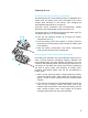
HDX noise reduction Progress you can hear. RF link Inherent noise of the RF link Transmitter Receiver This product family is equipped with HDX, the Sennheiser noise reduction system that reduces RF interference. It increases the signal-to-noise ratio in wireless audio transmission to more than 110 dB. HDX is a wideband compander system which compresses the audio signal in the transmitter in a 2:1 ratio (related to dB) to lift it above the inherent noise floor of the RF link.
Accessories and spare parts Only use original Sennheiser accessories and spare parts. ATTENTION: Components from other manufacturers (e.g.
MZW 1 Wind- and popshield MZQ 1 Microphone clamp BA 2015 Accupack L 2015 Charger for BA 2015 rechargeable battery KEN 8 color-coded identification caps for radiomicrophone SK 100 G2 / SK 300 G2 / SK 500 G2 bodypack transmitter ME 2 Clip-on microphone, condenser, omni-directional MKE 2-ew Clip-on microphone , black or beige, condenser, omni-directional ME 4 Clip-on microphone, condenser, cardioid ME 3 Headmic, condenser, super-cardioid DC 2 DC power adapter, for external 12 V DC powering (instead of two AA s
Specifications Temperature range -10°C to +55°C EK 1038 receiver Receiving frequencies 20 Frequency range 830–866 MHz (range E) (channel assignment: see table below) Switching bandwidth 36 MHz Modulation wideband FM Nominal/peak deviation ± 24 kHz / ± 48 kHz RF squelch 4 steps: Adjacent channel rejection > 70 dB Noise reduction system Sennheiser HDX AF frequency response 40 – 15.000 Hz Signal-to-noise ratio > 91 dB(A) THD at nominal deviation and 1 kHz < 1 %, typ. 0.
L 2015charger Input voltage: 10 - 20 V DC via hollow jack socket Hollow jack: Input current: 400 - 750 mA Charging voltage: 2 x 2.9 V Charging current: 2 x 700 mA Charging principle: ∆U method Deep discharge recovery charge Trickle charge rechargeable battery temperature monitoring Over/undercharge detection Charging time limit (max. 6 h) Charging time: approx. 2.
evolution wireless transmitters, G 2 Modulation wideband FM Frequency ranges 518–554, 626–662, 740–776, 786–822, 830–866 MHz Transmission/receiving frequencies 8 channel banks with up to 20 factory-preset channels each 1 channel bank with up to 20 freely selectable channels (1440 frequencies, tunable in steps of 25 kHz) RF output power at 50 Ω Power supply typ. 30 mW 2 AA size batteries, 1.
Channel assignment evolution wireless G2, generation 2 EK 1038 SKM 100 G2 SK 100 G2 SKP 100 G2 SKM 300 G2 SK 300 G2 SKM 500 G2 SK 500 G2 SKP 500 G2 channel bank 8 channel bank 8 channel bank 8 channel bank 8 menu menu menu menu “TUNE“ “CHAN“ “CHAN“ “CHAN“ channel range E frequency 1 863,100 1 1 1 1 2 863,500 2 2 2 2 3 864,300 3 3 3 3 4 864,900 4 4 4 4 5 854,100 5 5 5 6 854,600 6 6 6 7 855,300 7 7 7 8 856,200 8 8 8 9 857,300 9 9 10 859,700 10 10 11
EG-Konformitäts-Erklärung / EC Certificate of Conformity / Déclaration de conformité pour la CEE Certificato di conformitá comunitario / Declaración de Conformidad / EG-Conformiteitsverklaring SENNHEISER electronic GmbH & Co.
Important: Before putting the device into operation, please observe the respective country-specific regulations! The guarantee period for this Sennheiser product is 24 months from the date of purchase. Excluded are accessory items, rechargeable or disposable batteries that are delivered with the product; due to their characteristics these products have a shorter service life that is principally dependent on the individual frequency of use. The guarantee period starts from the date of original purchase.
Right of modifications reserved Sennheiser electronic GmbH & Co. KG 30900 Wedemark, Germany Phone +49 (5130) 600 0 Fax +49 (5130) 600 300 www.sennheiser.com Printed in Germany Publ.