SKM 500 Instruction manual
Contents Contents Important safety instructions ............................................... 2 The SKM 500 G3 radio microphone family ......................... 3 The frequency bank system ............................................. 3 Areas of application ............................................................ 4 Delivery includes ....................................................................... 5 Product overview ......................................................................
Important safety instructions Important safety instructions • Read this instruction manual. • Keep this instruction manual. Always include this instruction manual when passing the product on to third parties. • Heed all warnings and follow all instructions in this instruction manual. • Use only a cloth for cleaning the product. • Do not place the product near any heat sources such as radiators, stoves, or other devices (including amplifiers) that produce heat.
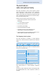
The SKM 500 G3 radio microphone family The SKM 500 G3 radio microphone family This radio microphone is part of the evolution wireless series generation 3 (ew G3). With this series, Sennheiser offers high-quality state-of-the-art RF transmission systems with a high level of operational reliability and ease of use. Transmitters and receivers permit wireless transmission with studio-quality sound.
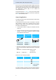
The SKM 500 G3 radio microphone family For an overview of the frequency presets, please refer to the supplied frequency information sheet. Updated versions of the frequency information sheet can be downloaded from the SKM 500 G3 product page on our website at www.sennheiser.com. The frequency banks “U1” to “U6” allow you to freely select and store frequencies. It might be that these frequencies are not intermodulation-free.
Delivery includes Delivery includes The packaging contains the following items: 1 SKM 500 G3 radio microphone incl. microphone head 2 AA size batteries, 1.
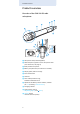
Product overview Product overview Overview of the SKM 500 G3 radio microphone 쐄 쐆 쐏 쐋 쐂 쐇 쐊 쐈 쐅 쐎 쐊 쐉 쐅 쐅 쐃 Microphone head (interchangeable) 쐇 Name and pick-up pattern of the microphone head (not visible here, see page 4) 쐋 Body of radio microphone 쐏 Battery compartment (not visible from outside) 쐄 Display panel, backlit in orange 쐂 Infra-red interface 쐆 Antenna 쐊 Color-coded protection ring; available in different colors 쐎 Operation and battery status indicator, red LED (lit = ON/flashing = LO
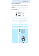
Product overview Overview of the displays After switch-on, the radio microphone displays the standard display “Frequency/Name”. For further illustrations and examples of the different standard displays, refer to page 15. The display backlighting is automatically reduced after approx. 20 seconds. 햲 햳 햴 햵 542.
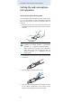
Putting the radio microphone into operation Putting the radio microphone into operation Inserting the batteries/accupack For powering the radio microphone, you can either use two 1.5 V AA size batteries or the rechargeable Sennheiser BA 2015 accupack (see “Accessories and spare parts” on page 30). Unscrew the lower part of the radio microphone from the radio microphone’s body 쐋 by turning it counterclockwise.
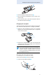
Putting the radio microphone into operation 씈 Close the battery compartment cover 씈. Push the battery compartment into the radio microphone’s body. Screw the lower part of the radio microphone back to the radio microphone’s body 쐋. Charging the accupack To charge the radio microphone with the BA 2015 accupack (see “Accessories and spare parts” on page 30) installed: Insert the radio microphone into the LA 2 charging adapter (see “Accessories and spare parts” on page 30) until it locks into place.
Putting the radio microphone into operation Do not touch the contacts of the radio microphone nor the contacts of the microphone head 쐃. The contacts can become dirty or damaged if touched. When unscrewing the microphone head 쐃 during operation, the muting function is automatically activated. “MUTE” appears on the display panel. When screwing the microphone head 쐃 back to the radio microphone, the muting is canceled. “MUTE” disappears from the display panel.
Putting the radio microphone into operation Changing the color-coded protection ring The color-coded protection ring 쐊 prevents the multifunction switch from accidental operation. Protection rings 쐊 in different colors are available as accessories (see “Accessories and spare parts” on page 30). The protection rings allow you to clearly identify each radio microphone. Remove the color-coded protection ring 쐊 as shown. 쐊 쐊 Put on a new protection ring 쐊 as shown.
Using the radio microphone Using the radio microphone CAUTION! Reduced transmission range If you touch the antenna 쐆 of the radio microphone, the transmission range will be considerably reduced! 쐆 Only hold the radio microphone by its body. To establish a transmission link, proceed as follows: 1. Switch the receiver on (see the instruction manual of the receiver). 2. Switch the radio microphone on (see next section).
Using the radio microphone You can switch the radio microphone on and deactivate the RF signal on switch-on. For more information, see next section. To switch the radio microphone off: If necessary, deactivate the lock mode (see page 14). ON/OFF Keep the ON/OFF button 쐉 pressed until “OFF” appears on the display panel. The red ON LED 쐎 goes off and the display panel turns off.
Using the radio microphone Deactivating the lock mode temporarily You can activate or deactivate the automatic lock mode via the “Auto Lock” menu item (see page 22). If the lock mode is activated, you have to temporarily deactivate it In order to be able to operate the radio microphone: Press the multi-function switch. “Locked“ appears on the display panel. Move the multi-function switch. “Unlock?” appears on the display panel. Press the multi-function switch again.
Using the radio microphone Selecting a standard display Move the multi-function switch to select a standard display. Contents of the display Selectable standard display 542.625 MHz ew500 G3 AF P MUTE B.Ch: 20.30 542.625 MHz AF “Frequency bank/Channel/ Frequency” P MUTE ew500 G3 B.Ch: 20.
Using the operating menu Using the operating menu A special feature of the Sennheiser ew G3 series is the consistent, intuitive menu structure of transmitters and receivers. As a result, adjustments to the settings can be made quickly – even in stressful situations, for example on stage or during a live show or presentation. Make use of the possibility to adjust settings via the operating menu of the receiver and to transfer these settings to the radio microphone.
Using the operating menu Overview of the operating menu Main menu “Menu” Sensitivity Frequency Preset Name Auto Lock Advanced Exit Display Extended menu “Advanced Menu” Tune RF Power Pilot Tone LCD Contrast Reset Software Revision Exit Function of the menu item Main menu “Menu” Sensitivity Adjusts the sensitivity “AF” (see page 20) Frequency Preset Sets the frequency bank and the channel (see page 21) Name Enters a freely selectable name (see page 21) Auto Lock Activates/deactivates the lock mode
Using the operating menu Working with the operating menu If the lock mode is activated, you have to deactivate it In order to be able to work with the operating menu (see page 14). By way of example of the “Sensitivity” menu, this section describes how to use the operating menu. Changing from a standard display to the operating menu Press the multi-function switch. The current standard display is replaced by the main menu. The last selected menu item is displayed.
Using the operating menu Exiting a menu item Change to the “Exit” menu item. Menu Exit Confirm your selection. You return to the next higher menu level. To directly return to the current standard display: ON/OFF Press the ON/OFF button.
Adjusting settings via the operating menu Adjusting settings via the operating menu Make use of the possibility to adjust settings via the operating menu of your receiver and to transfer these settings to the radio microphone. For more information, refer to the instruction manual of the receiver. The relevant information is marked with the sync icon.
Adjusting settings via the operating menu The following figures are a guide to the best settings: Transmission situation Sensitivity setting Loud music/vocals −48 to −18 dB Presentations −18 to −12 dB Interviews −12 to 0 dB Selecting the frequency bank and the channel manually – “Frequency Preset” Menu Frequency Preset B.Ch: 1. 1 Frequency Preset B.Ch: 1. 1 542.625 MHz Frequency B.Ch: 20. 1 533.
Adjusting settings via the operating menu The name can be displayed on the standard displays “Frequency/Name” and “Name/Frequency bank/Channel”. The name can consist of up to 8 characters such as: • letters (without pronounciation marks), • numbers from 0 to 9, • special characters and spaces. To enter a name, proceed as follows: Move the multi-function switch to select a character. Press the multi-function switch to change to the next segment/character or to store the complete entry.
Adjusting settings via the operating menu It is vital to observe the notes on frequency selection on page 26. Setting a transmission frequency for the current channel Move the multi-function switch until the “Tune” menu item appears. Press the multi-function switch. The frequency selection appears. Advanced Menu Tune 542.625 MHz Tune 542 .625 MHz B.Ch: U1. 1 Tune 544.625 MHz B.Ch: U1.
Adjusting settings via the operating menu Adjusting the transmission power – “RF Power” Advanced Menu RF Power RF Power Standard RF Power Low Call up “RF Power” Select the desired setting Store the setting “Stored” Via the “RF Power” menu item, you can adjust the transmission power in two steps. It is vital to observe the notes on the supplied frequency information sheet.
Adjusting settings via the operating menu Resetting the settings made in the operating menu – “Reset” Advanced Menu Reset Call up “Reset” Reset Yes Select the desired setting; apply the setting “Stored” When resetting the settings made in the operating menu, only the selected settings for the pilot tone and for the frequency banks “U1” to “U6” remain unchanged. For an overview of the factory-preset default settings, refer to the supplied frequency information sheet.
Synchronizing the radio microphone with a receiver Synchronizing the radio microphone with a receiver When synchronizing the radio microphone with a receiver, please observe the following: Only use a transmitter and a receiver from the same frequency range (see the type plate on the transmitter and the receiver). Make sure that the desired frequencies are listed in the enclosed frequency information sheet.
Cleaning the radio microphone Cleaning the radio microphone CAUTION! Liquids can damage the electronics of the radio microphone! Liquids entering the housing of the device can cause a short-circuit and damage the electronics. Keep all liquids away from the radio microphone. Use a cloth to clean the radio microphone from time to time. Do not use any solvents or cleansing agents.
Recommendations and tips Recommendations and tips ... for optimum sound • Hold the radio microphone in the middle of the microphone body. Holding it close to the sound inlet basket will influence the radio microphone’s pick-up pattern. • You can vary the bass reproduction by increasing/ decreasing the talking distance. • For best results, make sure that the sensitivity is correctly adjusted. ...
If a problem occurs ... If a problem occurs ... Problem Possible cause Possible solution Radio micro- Lock mode is phone activated cannot be operated, “Locked” appears on the display panel Deactivate the lock mode (see page 14). No operation indication Replace the batteries or recharge the accupack (see page 8). Batteries are flat or accupack is flat No RF signal Radio microphone Set the radio microat the and receiver are not phone to the same receiver on the same channel channel as the receiver.
Accessories and spare parts Accessories and spare parts The following accessories are available from your specialist dealer: Cat. No.
Specifications Specifications RF characteristics Modulation wideband FM Frequency ranges 516–558, 566–608, 626–668, 734–776, 780–822, 823–865 MHz (A–E, G, see page 3) Transmission frequencies 1,680 frequencies, tuneable in steps of 25 kHz 20 frequency banks, each with up to 32 factorypreset channels 6 frequency banks, each with up to 32 user programmable channels Switching bandwidth 42 MHz Nominal/peak deviation ± 24 kHz/± 48 kHz Frequency stability ≤ ±15 ppm RF output power at 50 Ω, switchable
Specifications In compliance with Europe EMC Radio Safety EN 301489-1/-9 EN 300422-1/-2 EN 60065 EN 62311 (SAR) Approved by Canada Industry Canada RSS 123 IC: 2099A-G3SKMEM limited to 806 MHz USA FCC-Part 74 FCC-ID: DMO G3SKMEM limited to 608 MHz Microphone heads MMD 935-1 MMD 945-1 MMK 965-1 Microphone type dynamic dynamic externally polarized dual diaphragm condenser microphone Sensitivity 2.5 mV/Pa 1.8 mV/Pa 5.7 mV/Pa / 1.
Specifications Polar diagram MMK 965-1 (cardioid) Polar diagram MMK 965-1 (super-cardioid) Frequency response curve MMD 935-1 dBV -30 -40 -50 -60 -70 -80 50 100 200 500 1.000 1k 2k 5k 10.000 10k 20k Hz 5k 10.000 10k 20k Hz Frequency response curve MMD 945-1 dBV -30 -40 -50 -60 -70 -80 50 100 200 500 1.
Index Index A Accupack charging 9 inserting 8 Activating/deactivating lock mode (Auto Lock) 22 pilot tone 24 Adjusting contrast (LCD Contrast) 24 input sensitivity (Sensitivity) 20 transmission power 24 Advanced Menu (extended menu) overview 17 settings 22 AF (audio level) 7 Auto Lock (activating/deactivating the lock mode) 22 B Batteries, inserting 8 Buttons (function of the ~) 16 C Channel assigning a frequency 23 overview 3 selecting (Frequency Preset) 21 selecting (Tune) 22 Charging accupack 9 batte
Index Lock mode activating/deactivating (Auto Lock) 22 deactivating temporarily 14 Locked (lock mode activated) 14 M Menu (main menu) overview 17 settings 20 Microphone heads changing 9 changing the color-coded protection ring 11 overview 4 pick-up patterns 4 polar diagrams/frequency response curves 32 suitable ~ 4 Modulation (input sensitivity/adjusting the sensitivity) 20 Multi-channel operation 26 N Name (entering a name) 21 O Offline operation (RF signal deactivated) 13 Online operation (RF signal ac
C M Y CM MY CY CMY K Sennheiser electronic GmbH & Co. KG Am Labor 1, 30900 Wedemark, Germany www.sennheiser.com Publ.