
Instruction manual Digital 9000 System


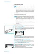


Table Of Contents
- Digital_9000_Manual_06_2017_EN
- Important safety instructions
- Digital 9000 – System overview
- Delivery includes
- EM 9046 receiver
- EM 9046 CAB cable set
- Antennas and antenna boosters
- GZL 9000 antenna cables
- SKM 9000/SKM 9000 COM radio microphone
- Microphone heads for the SKM 9000 radio microphone
- SK 9000 bodypack transmitter
- Microphones for the SK 9000 bodypack transmitter
- KA 9000 COM command adapter for the SK 9000 bodypack transmitter
- CI 1-4 line/instrument cable for the SK 9000 bodypack transmitter
- B 60/B 61 battery packs
- BA 60/BA 61 accupack
- L 60 charger
- Product overview
- EM 9046 receiver
- Antennas and antenna boosters
- GZL 9000 antenna cable
- SKM 9000/SKM 9000 COM radio microphone
- SK 9000 bodypack transmitter
- KA 9000 COM command adapter for the SK 9000 bodypack transmitter
- BA 60 accupack
- BA 61 accupack
- B 60 battery pack
- B 61 battery pack
- L 60 charger
- Preparing the EM 9046 receiver for use
- Preparing the A/AB/AD 9000 antennas and/or antenna boosters for use
- Preparing the SKM 9000 radio microphone for use
- Preparing the SK 9000 bodypack transmitter for use
- Preparing the L 60 charger for use
- Cascading several chargers
- Setting up or mounting the charger
- Preparing the Digital 9000 system for use
- Using the EM 9046
- Using the SKM 9000
- Using the SK 9000
- Using the L 60
- Cleaning and maintaining the Digital 9000 system
- If a problem occurs ...
- Specifications

Digital 9000 | 81
Using the EM 9046
왘 Assess the result of the walk
test:
Interference due to extraneous RF signals and low antenna signals can
impede the evaluation of a transmitter’s RF signal. In this case, the window
displaying the recorded antenna signals is highlighted in light gray.
왘 Reposition the antennas to minimize interference and to optimize the
reception of transmission signals.
왘 Call up the “RF level recorder” menu item again and repeat the walk
test.
Extended menu “Transmitter setup”
Via the extended menu “Transmitter setup”, you can adjust the transmit-
ter settings and then synchronize them via infra-red.
The menu items allow you to adjust settings over the entire value range of
the Digital 9000 transmitters. Please note, however, that the actual values
are determined by the hardware configuration of your transmitters (fre-
quency range, type of microphone head being used (SKM), type of Senn-
heiser microphone or cable being used (SK), etc.).
If you adjust settings that are not supported by the transmitters’ current
hardware configuration, the value actually adopted by the transmitter is
written back to the menu item of the extended menu “Transmitter setup”.
If you transfer a frequency range that is not supported by your transmit-
ter, “Sync Fail” is displayed in the menu selection of the receiver’s display
panel.
Modifications made via the “Transmitter setup” menu item of the EM 9046
must be synchronized via infra-red.
Modifications made directly on the transmitters have direct effect on the
menu items of the extended menu “Transmitter setup” of the EM 9046.
For details on the adjustment ranges of your transmitters, refer to the
description of the transmitters’ operating menu.
Start fullscan
MHz
CH 1
790
0:00 0:30 1:00 1:30 2:00
min
000
Showing RF level or channel 1
RF IN A
RF IN B
no signal
cmd
A
B
rf level rec
Low antenna signals: RF signal cannot be
evaluated, the window is highlighted in gray
Diversity evaluation
Antenna signals
COMMAND button
has been pressed