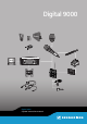
Digital 9000 WSM Digital 9000 System instruction manual
Content Content Important safety instructions ..................................................6 Digital 9000 – System overview ........................................... 11 EM 9046 receiver ......................................................................................12 Antennas and antenna boosters ...........................................................12 SKM 9000 radio microphone/ SK 9000 bodypack transmitter ..............................................................13 L 60 charger ...
Content Positioning the receiving antennas ....................................................... 39 Connecting the receiving antennas/antenna boosters ..................... 40 Adjusting the receiving antennas/antenna boosters ....................... 40 Preparing the SKM 9000 radio microphone for use .............................40 Changing the microphone head .............................................................42 Preparing the SK 9000 bodypack transmitter for use .........................
Content SKM 9000 radio microphone ..................................................................111 SK 9000 bodypack transmitter .............................................................111 L 60 charger .............................................................................................112 Specifications .........................................................................
Digital 9000 Important safety instructions A 9000 AB 9000 ME 9002 ME 9004 ME 9005 ... AD 9000 GZL 9000-A5 GZL 9000-A10 GZL 9000-A20 EM 9046 B 60 BA 60 SKM 9000 SKM 9000 COM WSM L 60 EM 9046 AAO EM 9046 DAO SK 9000 B 61 BA 61 KA 9000 COM EM 9046 CAB MKE 1 MKE 2 ...
Important safety instructions Important safety instructions 1. Read these instructions. 2. Keep these instructions. Always include these instructions when passing the apparatus on to third parties. 3. Heed all warnings. 4. Follow all instructions. 5. Do not use this apparatus near water. 6. Clean only with a dry cloth. 7. Do not block any ventilation openings. Install in accordance with the manufacturer’s instructions. 8.
Important safety instructions Hazard warnings on the rear of the receiver The label shown on the left is attached to the rear of the EM 9046. The symbols on this label have the following meaning: Presence of uninsulated dangerous voltage within the EM 9046’s enclosure that may be of sufficient magnitude to constitute a risk of electric shock. Never open the EM 9046 as there is a risk of electric shock. There are no user serviceable parts inside. Never attempt to change the modules of the EM 9046 yourself.
Important safety instructions Safety instructions for A/AB/AD 9000 antennas/antenna boosters Use safety wires to protect the receiving antennas against tipping/dropping. The safety wires, rope terminations and coupling links must comply in their dimensioning and condition with the regulations and standards of the country in which they are used! Safety instructions for lithium-ion rechargeable batteries If abused or misused, the rechargeable batteries of the SK 9000/SKM 9000 may leak.
Important safety instructions Only use rechargeable batteries specified by Sennheiser. Dispose of rechargeable batteries at special collection points or return them to your specialist dealer. Store the product in a cool and dry place at room temperature (approx. 20 °C/ 68 °F). Remove the rechargeable batteries if the product will not be used for extended periods of time.
Digital 9000 – System overview Digital 9000 System overview Digital 9000 – System overview A 9000 AB 9000 ME 9002 ME 9004 ME 9005 ... AD 9000 GZL 9000-A5 GZL 9000-A10 GZL 9000-A20 EM 9046 B 60 BA 60 SKM 9000 SKM 9000 COM WSM L 60 EM 9046 AAO EM 9046 DAO SK 9000 B 61 BA 61 KA 9000 COM EM 9046 CAB Digital 9000 – System overview ..................................... EM 9046 receiver ............................................................ Antennas and antenna boosters .......................
Digital 9000 – System overview The Digital 9000 system The Digital 9000 system is characterized by its high transmission reliability and easy of use. The large switching bandwidth as well as various different connection possibilities offer great flexibility in daily use.
Digital 9000 – System overview SKM 9000 radio microphone/ SK 9000 bodypack transmitter The SKM 9000 and SK 9000 transmitters offer great ease of use and can easily be adapted to any transmission situation: • Rugged housing • Input gain adjustable in 3 dB steps • Switchable 1 kHz test tone, useful for level matching the system and for the walk test • High accuracy of charge status display (B/BA 60/61) or remaining operating time display (B 60/61) • Detection and support of the type of microphone he
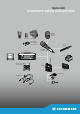
Delivery includes Delivery includes You can make up your own Digital 9000 system with the following components: EM 9046 receiver 1 EM 9046 receiver fixedly equipped with - PSU power supply unit - CCC core clock controller - ASP antenna splitter - AUX blanking plate optionally equipped with - up to eight EM 9046 DRX receiver modules and - AAO/DAO analog/digital audio out modules 3 mains cables (with EU, UK and US plug) 1 CAT 5 Ethernet cable 1 instruction manual 1 CD ROM with - “Wireless Systems Manager” (
Delivery includes SKM 9000/SKM 9000 COM radio microphone 1 SKM 9000 radio microphone or 1 SKM 9000 COM radio microphone 1 MZQ 9000 microphone clamp 1 supplement “Framework requirements and restrictions on frequency usage in Europe” 1 instruction manual You additionally require microphone heads as well as a BA 60 accupack and/or a B 60 battery pack. If you are using the BA 60 accupack, you will also require an L 60 charger.
Delivery includes B 60/B 61 battery packs 1 B 60 battery pack for SKM 9000 radio microphone or 1 B 61 battery pack for SK 9000 bodypack transmitter 1 instruction manual BA 60/BA 61 accupack 1 BA 60 accupack for SKM 9000 radio microphone or 1 BA 61 accupack for SK 9000 bodypack transmitter 1 instruction manual L 60 charger 1 L 60 charger for BA 60/BA 61 accupacks 1 instruction manual For powering the L 60 charger, you require the NT 3-1 mains unit with a country-specific mains cable (EU, UK or US version)
Product overview Product overview EM 9046 receiver Overview of the front panel 1 2 3 4 5 6 789 P ON 0 ABCD E F M G 2 LK J IH 1 Rack-mount “ear” with handle D Infra-red interface 2 Ventilation openings E LED 3 Standby button F button 4 USB socket G Jog dial for menu control 5 net LED (network) H Headphone volume control 6 clock LED (external word clock synchronization) I Headphone socket , ¼" (6.
Product overview Overview of the rear panel The overview of the rear panel shows an EM 9046 receiver equipped with the fixed PSU, CCC and ASP modules and the optional DRX, DAO and AAO modules. The configuration shown is an example configuration. The interchangeable modules are highlighted in color.
Product overview For the pin assignment of the XLR-3 and sub-D sockets of the EM 9046, refer to the chapter “Specifications” on page 123. Overview of the displays and the clock LED 1 A1.7 A1.7 2 A1.7 A1.7 3 A 4 4 HD fs 3:10 5 6 A fs 7 3:10 8 CH3 473 800 9 0 CH3 CH3 473 800 473 800 CH3 473 800 1 Frequency preset display A1.7 A Selected booster (type A or type B) 1 Selected booster frequency range (1 ... 8) (bandwidth: 24 MHz) 7 Frequency preset (1 ...
Product overview 8 Display for charge status of accupack/battery pack 9 Channel name display 0 Receiving channel display A Channel status displays (examples) The clock LED The clock LED 20 | Digital 9000 6 provides information on the following states: clock LED Meaning lights up The receiver’s digital audio output is synchronized with an external word clock signal.
Product overview Antennas and antenna boosters 1 1 5 2 2 5 6 3 2 4 4 5 A 9000 3 RF out 4 Filter Com on 4 9 8 7 AD 9000 AB 9000 1 Antenna surface 5 Type plate (not visible here) 2 and 9: “Com” and “On” LED - red: error - green: manual mode - blue: automatic mode (EM 9046-controlled) - white: firmware update in progress 6 RF in socket (N-type) (AB 9000 only) 7 Stand adapter 8 “Filter” rotary switch (see below) 3 Hole for connection of safety wires 4 RF out socket (N-type) If you are
Product overview GZL 9000 antenna cable 1 3 2 1 GZL cable, available in lengths of 5 m, 10 m and 20 m 3 N-type socket 2 N-type connector SKM 9000/SKM 9000 COM radio microphone 1 2 4 5 6 7 8 90 D 3 D 1 Microphone head A SET button 2 Contacts of microphone head 4 COMMAND button* (SKM 9000 COM) B ON/OFF button with ESC function (cancel) - lights up constantly: radio microphone is operational 5 Display panel C Antenna 6 Infra-red interface D Catches for accupack/battery pack 3 Contacts of
Product overview Overview of the standard display after switch-on After switch-on, the radio microphone displays the currently selected standard display (here: “Frequency”). For an overview of all standard displays, refer to page 90. 1 2 3 4 5 6 480.
Product overview SK 9000 bodypack transmitter 1 2 3 4 5 C 0 6 7 8 B 9 9 D 0 A E F 1 3-pin special audio socket for - Sennheiser microphones - CI 1-4 Sennheiser instrument cable - KA 9000 COM command adapter 2 ON/OFF button with ESC function (cancel) 3 ON LED - lights up constantly: transmitter is operational - flashes regularly: remaining operating time is less than 30 minutes - flashes with high levels: audio signal is excessively high 4 Antenna socket 5 Infra-red interface 6 DOWN button 24 |
Product overview Overview of the standard display after switch-on After switch-on, the bodypack transmitter displays the currently selected standard display (here: “Frequency”). For an overview of all standard displays, refer to page 99. 1 2 3 4 5 6 480.
Product overview KA 9000 COM command adapter for the SK 9000 bodypack transmitter 2 3 4 1 1 3-pin special audio connector 3 3-pin special audio socket 2 COMMAND button 4 Connection cable, length: 1.
Product overview BA 61 accupack 1 2 1 3 1 Snap-in elements 3 Guide rail 2 Charging and data contacts B 60 battery pack 3 2 1 4 1 Battery compartment for 2 AA size batteries 3 Antenna 4 Data contacts 2 Snap-in elements Digital 9000 | 27
Product overview B 61 battery pack 1 2 1 3 5 4 2 1 Snap-in elements 3 Guide rail 2 Data contacts 4 Battery compartment for 3 AA size batteries 5 Cover 28 | Digital 9000
Product overview L 60 charger 3 4 2 5 1 5 1 Status LED 3 Charging compartments for BA 61 or BA 60 accupacks 2 DC input socket for connection of NT 3-1 mains unit 4 Ventilation openings 5 Rails for cascading up to 4 chargers Indications of the status LED Status LED 1 Meaning off Standby mode/no connection to the mains red Accupack is being charged, capacity obtained is approx. 0-70% orange Accupack is being charged, capacity obtained is approx.
Digital 9000 Preparing for use A 9000 AB 9000 ME 9002 ME 9004 ME 9005 ... AD 9000 Preparing the Digital 9000 system for use GZL 9000-A5 GZL 9000-A10 GZL 9000-A20 EM 9046 B 60 BA 60 SKM 9000 SKM 9000 COM WSM L 60 EM 9046 AAO EM 9046 DAO SK 9000 B 61 BA 61 KA 9000 COM EM 9046 CAB Preparing the Digital 9000 system for use ..........31 Preparing the EM 9046 receiver for use ......................32 Setting up the receiver or mounting it into a 19" rack ............................................
Preparing the Digital 9000 system for use Preparing the EM 9046 receiver for use Setting up the receiver or mounting it into a 19" rack Setting up the receiver on a flat surface CAUTION Risk of staining of furniture surfaces! Furniture surfaces can be treated with varnish, polish or synthetics which might cause stains when they come into contact with other synthetics. Despite a thorough testing of the synthetics used by us, we cannot rule out the possibility of staining.
Preparing the Digital 9000 system for use To mount the receiver into a 19" rack: 왘 Mount rack rails that are designed to carry the total weight of the EM 9046. Slide the receiver onto the rack rails and screw it to the front of the rack using 2 screws per side (screws to be ordered separately). Connecting devices to the analog audio outputs When equipped with an AAO analog audio out module, the EM 9046 receiver has 8 analog transformer balanced audio outputs.
Preparing the Digital 9000 system for use Connecting devices to the digital audio outputs When equipped with an DAO digital audio out module, the EM 9046 receiver has 8 digital balanced audio outputs. The signals are output in AES3 format. 왘 Connect the digital audio inputs of an external device to the XLR-3 sockets A or the sub-D socket B of the EM 9046.
Preparing the Digital 9000 system for use Daisy chaining receivers EM9046 ANT A ANT B The EM 9046 receivers feature an integrated antenna splitter so that up to four receivers can be daisy chained. This allows you to use two antennas/ antenna boosters for up to four receivers. In this case, all receivers have to use the same booster frequency range. 왘 Use GZL 9000 antenna cables to connect two antennas via antenna boosters to the RF IN N-type sockets E and F of the first receiver.
Preparing the Digital 9000 system for use Connecting external word clock signals The EM 9046 receiver supports external word clock sampling rates of 44.1 kHz, 48 kHz, 88.2 kHz and 96 kHz. If you have installed a MAN card, you can alternatively use the card‘s word clock as external word clock generator. EM9046 A B C D E 9 BNC (Word Clock in) F 왘 (This step is not required if you use the word clock signal of a built-in MAN card.
Preparing the Digital 9000 system for use – You use both network sockets (LAN UP and LAN DOWN) of the receivers. This causes the receivers to act as a switch. You do not require an external switch. – The Spanning Tree Protocol (STP) and/or the Rapid Spanning Tree Protocol, (RSTP) are used to detect and deactivate redundant paths in the local network. Redundant paths are caused by faulty cabling (unintentional cabling loops).
Preparing the Digital 9000 system for use Connecting the receiver to the mains CAUTION Damage to the device due to electric current! If you connect the receiver to an unsuitable power supply, this can cause damage to the device. 왘 Use the supplied mains cable to connect the receiver to the mains (100 to 240 V AC, 50 or 60 Hz). 왘 Ensure a reliable mains ground connection of the receiver – especially when you are using multi-outlet power strips or extension cables.
Preparing the Digital 9000 system for use Preparing the A/AB/AD 9000 antennas and/or antenna boosters for use Antennas and antenna boosters of the Digital 9000 series are available in two variants: A1–A8 and B1–B8.
Preparing the Digital 9000 system for use Connecting the receiving antennas/antenna boosters 왘 Use GZL 9000 antenna cables. Sennheiser GZL 9000 antenna cables are available in lengths of 5 m, 10 m and 20 m. A/AB/AD 9000: 왘 Connect the RF out sockets 4 of the antennas/antenna boosters used to the N-type sockets RF IN A E and RF IN B F of your EM 9046. AB 9000: 왘 Connect the RF IN socket 6 of the two antenna boosters to one antenna each. 왘 Use short cables to keep the cable attenuation as low as possible.
Preparing the Digital 9000 system for use Inserting batteries into the B 60 battery pack 왘 Insert the batteries (see diagram). Observe correct polarity when inserting the batteries. Only insert high-quality AA size batteries (e.g. lithium or alkaline batteries) into the B 60 battery pack. Do not insert individual rechargeable batteries such as NiMH cells.
Preparing the Digital 9000 system for use Changing the microphone head CAUTION Damage to the microphone head! If you touch contacts, they can become dirty or damaged. 왘 Do not touch the contacts of the radio microphone nor the contacts of the microphone head. 왘 Unscrew the microphone head 1. 1 With some microphone heads, the upper part of the sound inlet basket can be unscrewed. To fully unscrew the microphone head, always hold it as shown.
Preparing the Digital 9000 system for use CAUTION Damage to the bodypack transmitter and/or the accupack/battery pack! If you touch the following contacts, they can become dirty or damaged: • Contacts for supply voltage and data contacts of the bodypack transmitter • Charging and data contacts of the BA 61 accupack • Data contacts of the B 61 battery pack 왘 Do not touch the contacts of the bodypack transmitter nor the contacts of the BA 61 accupack/B 61 battery pack.
Preparing the Digital 9000 system for use To attach the accupack/battery pack: 왘 Slide the accupack/battery pack onto the guide rails of the bodypack transmitter until it locks into place with an audible click. The bodypack transmitter is then ready for operation. 1 2 When removing the accupack/battery pack, the settings of the radio microphone are retained.
Preparing the Digital 9000 system for use Connecting the antenna 왘 Only use the supplied antenna. 왘 Connect the antenna as shown: 1 2 Connecting the KA 9000 COM command adapter Using the KA 9000 COM command adapter, you can change the audio channel on the EM 9046 receiver via remote control, e.g. for stage directions. 왘 Connect the 3-pin special audio connector 1 of the KA 9000 COM to the 3-pin special audio socket 1 of the SK 9000.
Preparing the Digital 9000 system for use Preparing the L 60 charger for use Cascading several chargers Up to 4 L 60 charger can be cascaded together and can be powered by the NT 3-1 mains unit. 왘 Prepare the L 60 chargers: – Make sure that the chargers are disconnected from the mains. – Unscrew the two screws 6 at the bottom of one charger. – Tilt the charger to the side and slide out the rails 5 completely. – Tighten the two screws 6. 7 6 5 왘 Unscrew the two screws 7 at the bottom of a second charger.
Preparing the Digital 9000 system for use To fix the charger securely in place: 왘 Fix the charger by screwing screws (fillister head self-tapping screws as per DIN 7049, ST 3.5 x 32) through the four holes 8 at the bottom of the charger. 8 34 m m 36 mm 8 To ensure reliable operation of the L 60 and efficient charging of the BA 60/61: 왘 Make sure that the ambient temperature of the charger is within the operating temperature range (see page 122).
Digital 9000 Using the EM 9046 Using the EM 9046 Using the EM 9046 ............................................................. 49 Using the EM 9046 receiver .......................................... 50 Switching the receiver on/off ....................................... 50 “sys”, “ch”, “live” – operating modes at a glance ... 51 Basic functions of the Sennheiser operating menu . 51 Displays of the Sennheiser operating menu ............. 52 Error and warning messages ...................................
Using the EM 9046 Using the EM 9046 receiver Switching the receiver on/off To switch the receiver on: 3 왘 Make sure the ON/OFF switch 1 is set to position “1”. 왘 Press the standby button 3. The receiver’s operating system is loaded. During loading, the LED of the standby button 3 flashes red and the display panel shows the Sennheiser start screen. Then, an automatic calibration of the cable attenuation is performed (see page 64).
Using the EM 9046 “sys”, “ch”, “live” – operating modes at a glance “live” operating mode – Live transmission live In this mode, you can check, among other things, the following parameters during transmission: • RF level • True bit diversity evaluation • Audio level • Charge status of the BA/B 60/61 accupack/battery pack • Remaining operating time of the BA 60/61 accupack More information on the “live” operating mode can be found from page 84 onwards.
Using the EM 9046 In addition, in “ch” operating mode, the channel 1–8 button M and the multiple channel selection button + K are available: Channel 1–8 button and multiple channel selection button + 왘 Select a channel or press the multiple channel selection button + K and then select several channels simultaneously. + The channel 1–8 button M and the multiple channel selection button + K are also available in “live” operating mode.
Using the EM 9046 If you call up a menu item by pressing the jog dial G, the menu selection is framed in blue: Menu item selected Audio outputlevel output level Menu item called up Audio outputlevel output level When a menu item has only a few options to choose from, this can be done directly via the menu selection (see for example the “word clock” menu item on page 64).
Using the EM 9046 Error and warning messages Error and warning messages are displayed in white letters. The display panel is highlighted in orange. Example: “Frequency out of booster range” warning message Frequency out of booster range You can hide error/warning messages by pressing the esc button L. In order to check if errors or warnings are still present, you can call up the “System check” menu item in the extended menu “Service setup” of the system menu. For more information, refer to page 70.
Using the EM 9046 “sys” operating mode – Configuring the system In “sys” operating mode, you can configure the transmitters and the receiver.
Using the EM 9046 Extended menu “Service setup” HW setup Firmware Legal Page Displays the hardware configuration and status 70 Displays the firmware versions and updates the firmware of the transmitters and boosters 73 License and copyright information 75 Main menu “System setup” To get into the main menu: 왘 Select the “sys” operating mode. “Frequency scan” – Performing a frequency scan of all 8 frequency ranges The main menu contains two menu items that allow you to perform a frequency scan: 1.
Using the EM 9046 왘 Turn the jog dial G until the text “start scan” at the bottom margin of the screen is highlighted in blue: Startfrequency fullscan scan Start freq scan B1 630 B2 B3 B4 B5 B6 Start scan 0 B7 B8 0 0 0 0 0 0 0 0 0 0 0 0 0 0 0 0 0 0 0 0 0 0 0 0 0 0 0 0 0 0 0 654 654 678 670 694 694 718 710 734 734 758 750 774 774 798 MHz active Noise Level Zone HD HD/LR LR/HD Start scan start full scan LR RF IN A B 왘 Start the frequency scan by press
Using the EM 9046 The selection of a suitable booster frequency range depends on several factors: • Required number of transmission links • Sufficient number of unused frequency presets • Sufficient number of transmitters of the correct type (in this example, transmitters of type B1–B4 or B5–B8, see page 39) • Recommended transmission mode “HD” or “LR”: “HD (High Definition)”: Transmission of an audio signal without audio data compression. As a result, the audio signal remains pure and unadulterated.
Using the EM 9046 Example 2: 6 transmitters of type B1–B4, 8 transmitters of type B5–B8 Let us assume that you have only 6 transmitters of type B1–B4 but 8 transmitters of type B5–B8. Is there a sufficient number of transmitters of the correct type? – – – – The number of transmitters is sufficient but the booster frequency range B6 does not provide a sufficient number of unused frequency presets in interference zone “HD”.
Using the EM 9046 “Range detail scan” – performing an optional frequency scan of the active frequency range and assigning frequency presets to the channels 왘 Call up the “Range detail scan” menu item. The activated booster frequency scan and the result of the last frequency scan (“Frequency scan” or Range detail scan”) are displayed. “Select channel or press SET to scan” appears in the menu selection. please select booster range Select channel or press SET to scan. n.. detail scan 774.000 778.000 782.
Using the EM 9046 There are three ways to assign a frequency preset or a frequency to a channel: 1. You can automatically select the frequency preset with the lowest interference level. This is the quickest and most convenient way of assigning a frequency to a channel. 2. You can manually select a frequency preset. 3. You can manually set an arbitrary frequency.
Using the EM 9046 Manually setting a frequency If you do not want to use a frequency preset but you want to set a frequency yourself, proceed as follows: 왘 Press the jog dial. Each time you press the jog dial, you switch between – the “Preset” settings, – the frequency setting in MHz steps and – the frequency setting in kHz steps. 왘 First set the frequency in MHz steps by turning the jog dial. Press the jog dial to confirm your setting. 왘 First set the frequency in kHz steps by turning the jog dial.
Using the EM 9046 “Audio output level” – Adjusting the analog output levels Audio output level output level EM 9046 AAO EM 9046 DAO 1 2 3 4 0 0 0 0 5 6 7 8 0 0 0 0 Analog multicore 00 0 Via the “Audio output level” menu item, you can adjust the level of all or individual channels of the Analog Audio Out (AAO) module. 왘 Call up the “Audio output level” menu item.
Using the EM 9046 “Word clock” – Configuring the word clock internal: 44.1kHz word clock Via the “word clock” menu item, you can ... • switch between the following word clock signals: – internally generated word clock signal – external word clock signal – word clock signal of a built-in MAN card • adjust the sampling rate (44.1 kHz, 48.0 kHz, 88.2 kHz or 96.0 kHz) with which – with an internally generated word clock signal – analog signals are digitalized and output at the XLR-3 sockets A.
Using the EM 9046 Display Status of the cable attenuation “ok” The cable attenuation has been measured and is automatically compensated for. “Too high” The cable attenuation has been measured and is too high. It cannot be automatically compensated for. The reception of weaker signals is compromised. 왘 Check and optimize the installation between the EM 9046 and the antenna boosters. Always use GZL 9000 system cables to obtain optimum attenuation values.
Using the EM 9046 Menu Menu item Page Main menu “Channel setup” Frequency 77 Name 78 Cmd mode 78 Encryption 79 Gain 82 Low cut 82 Display 83 Lock 83 Cable 83 The following settings/values are not saved: • time and date settings of the “Date & time” menu item (see page 69) and • operating hours (displayable via the “op hours” menu item, see page 69). “Network” – Configuring the network EM 9046 Name IPv4 address 169.254.92.238 network Slot analog: EM 9046 IPv4 address: auto 192.
Using the EM 9046 “Screensaver” The “Screensaver” menu item adjusts the “Brightness” to the lowest (menu-selectable) value, independent of the user-set “Brightness” value. The “Screensaver” is activated after 30 minutes if the following conditions are met: • The “Screensaver” menu item is set to ON. • No entry via button or jog dial for 30 minutes. • No RXD card connected to a transmitter for 30 minutes.
Using the EM 9046 In the extended menu, you can adjust the following settings: “Factory reset” – Resetting the receiver to the factory defaults Factory reset factory reset Via the “factory reset” menu item, you can reset your receiver to the factory default settings. To do so, follow the prompt on the main screen to press the button F for 5 seconds.
Using the EM 9046 The following settings/values are not deleted: • time and date settings of the “Date & time” menu item (see page 69) and • operating hours (displayable in the “op hours” menu item, see page 69).
Using the EM 9046 The following events are logged: • System starts and (controlled) stops • System error messages (error screens) • Channel warnings • Each storing of settings with specification of the changed values • Each modification of values via the WSM software • Each synchronization with a transmitter • Software updates “System check” – Displaying current error and warning messages System check: system check Via the “system check” menu item, you can display current error and warning messages.
Using the EM 9046 Call up this menu item to get detailed information on error and warning messages. Show alerts Boosters RF-IN B: no booster connected Modules Fans Network Wordclock CH1 If you call up the first menu entry “Show alerts”, the warning message is displayed again and the display panel is highlighted in orange.
Using the EM 9046 “Hw setup” – Displaying the EM 9046’s hardware configuration and confirming a modified configuration Modules ok Hw setup While the operating system of the EM 9046 starts up, it checks the receiver’s hardware configuration for modifications. Modifications of the hardware configuration are indicated by warning messages.
Using the EM 9046 If you have extended the EM 9046’s hardware configuration, this is displayed in the “hw setup” menu item with the status “added”: p Slot Module Type State RX1 EM 9046 DRX ok RX2 EM 9046 DRX ok RX3 EM 9046 DRX ok RX4 EM 9046 DRX ok RX5 EM 9046 DRX ok RX6 EM 9046 DRX ok RX7 EM 9046 DRX ok RX8 EM 9046 DRX ok OUT1 EM 9046 AAO ok OUT2 EM 9046 DAO added In both cases, the “Press SET to confirm” button is highlighted in blue.
Using the EM 9046 The currently installed firmware version and the installable firmware (“Update to Firmware”) of connected boosters/transmitters are displayed in the “Antenna Booster” area of the main screen. To update the firmware of the boosters: 왘 Using the jog dial, select the “Antenna Booster” area of the main screen. The “Antenna Booster” area is highlighted in blue. 왘 Press the jog dial. The firmware is updated. The update process can take up to 40 seconds.
Using the EM 9046 During the update, the following icon appears on the display panel of your transmitter: If the firmware update was successful, this icon disappears and “Transmitter fw update successfull” appears in the menu selection of the receiver’s display panel. If the update fails, the following icon appears on the display panel of your transmitter: In addition, the error message “Error: Transmitter fw update failed” briefly appears in the menu selection of the receiver’s display panel.
Using the EM 9046 “ch” operating mode – Configuring channels In “ch” operating mode, you can configure channels. Some of the settings that can be made can be synchronized via infra-red between the receiver and the transmitters. These settings are marked with a in the column (see also next page). In “ch” operating mode, you can also select channels for headphone monitoring. To do so, proceed as described on page 84.
Using the EM 9046 To synchronize the settings with your transmitters via infra-red: 왘 Select one of the channels 1–8. 왘 Switch on the transmitter to which you want to assign this channel. 왘 Press the button J on the EM 9046. The receiver switches to synchronization mode and the flashes. LED B 왘 Place the transmitter’s infra-red interface in front of the infra-red interface D of the receiver. Maintain a distance of approx. 10–20 cm between the infra-red interfaces.
Using the EM 9046 If you manually set the frequency to a value outside the current 24 MHz booster frequency range and confirm you setting by pressing the button F, the following error message appears: Frequency out of booster range “Name” – Entering a channel name G U I T A R 1 name Via the “Name” menu item, you can enter freely selectable names.
Using the EM 9046 The following settings are possible: Setting Effect “on” The transmitter’s audio signal is output via both its audio channel (XLR-3 sockets C 1 ... 8) and the corresponding channel of the sub-D socket D. Pressing the COMMAND button on the SKM 9000 COM or KA 9000 COM has no effect. “add” The transmitter’s audio signal is output via its audio channel (XLR-3 sockets C 1 ... 8).
Using the EM 9046 To protect the audio signal against eavesdropping from other receivers: 왘 In the “Encryption” menu item, select “On” and press the to store your setting. 왘 Synchronize the setting via infra-red (see page 77).
Using the EM 9046 왘 Assess the result of the walk test: StartRF fullscan Showing level or channel 1 rf level rec Diversity evaluation A B RF IN A RF IN B no signal cmd Antenna signals 0:00 0:30 1:00 1:30 min 2:00 790 000 MHz CH 1 Low antenna signals: RF signal cannot be evaluated, the window is highlighted in gray COMMAND button has been pressed Interference due to extraneous RF signals and low antenna signals can impede the evaluation of a transmitter’s RF signal.
Using the EM 9046 “RF mode” – Adjusting the transmission mode HD (high definition) rf mode The “RF mode” menu item allows you to adjust the transmission mode: “HD (High Definition)”: Transmission of an audio signal without audio data compression. As a result, the audio signal remains pure and unadulterated. In “HD” transmission mode, the range can be restricted compared to “LR” transmission mode.
Using the EM 9046 After synchronization with the transmitter, the value actually adopted by the transmitter is written back to the menu item. “Display” – Selecting the standard display for the transmitters frequency display The “Display” menu item allows you to activate one out of 3 standard displays: “Name”, “Preset” or “Frequency”. The “Name” standard display is factory preset.
Using the EM 9046 Via the “Cable” menu item, you can emulate the lengths of instrument cables in 3 steps: “type1”, “type2” and “type3”. If you select “line”, no emulation takes place. “live” operating mode – Using a configured system In “live” operating mode, you can select channels for headphone monitoring and synchronize the transmitters and the receiver. To prepare headphone monitoring: 왘 Connect headphones as described on page 38. 왘 Observe the warnings given there.
Digital 9000 Using the SKM 9000 Using the SKM 9000 Using the SKM 9000 ................................................ 85 Switching the SKM 9000 on/off .................................. 86 Activating/deactivating the automatic lock mode (Autolock) ........................................................................ 87 Basic functions of the Sennheiser operating menu . 88 Overview of the status displays .................................. 88 Overview of the menu items ................................
Using the SKM 9000 Using the SKM 9000 Before using your radio microphone, ask the relevant wireless regulatory authority for the exact frequency allocations and apply for an individual license if necessary. The supplied supplement “Framework requirements and restrictions on frequency usage in Europe” provides an overview of the different European framework requirements and restrictions on frequency usage.
Using the SKM 9000 Switching on the SKM 9000 on and checking the set frequency before the RF signal is activated 왘 Switch on the SKM 9000 by keeping the ON/OFF button B pressed until the “Name” standard display appears. The RF signal is not activated and the transmission mode display “HD”/ “LR” flashes. If you call up the “Tune” or “Preset” menu item within the next 10 seconds, the RF signal remains deactivated until you exit the menu item.
Using the SKM 9000 While this display is shown (about 2 seconds), you can temporarily deactivate the lock mode: 왘 Press the UP button or the DOWN button . The following display appears on the display panel: 왘 Press the SET button . The lock mode is temporarily deactivated. The lock mode icon 5 flashes. 480.000 3:59 - If you do not press a button, the lock mode is activated again after 2 seconds. The lock mode icon 5 lights up constantly again.
Using the SKM 9000 Status display 6:59 4:40 2:20 Meaning BA/B 60 accupack/battery pack: charge status 100% | 70% | 30% BA 60 accupack: remaining operating time in h:mm Accupack/battery pack is completely discharged, transmitter is not operational Setting is being stored Firmware is being updated Firmware update has failed Overview of the menu items Icon Name Function Tune Sets a frequency 89 Preset Selects a frequency preset 90 Name Enters a name 90 Gain Adjusts the input gain 90
Using the SKM 9000 “Preset” – Selecting a frequency preset Via the “Preset” menu item, you can select a frequency preset from the active booster frequency range or the frequency preset “U” (see also the “Tune” menu item). To activate a different booster frequency range: 왘 Proceed as described from page 56 onwards. You first activate the booster frequency range on the EM 9046. If you then synchronize the transmitter and the receiver, the booster frequency range on the transmitter will also be activated.
Using the SKM 9000 “Reset” – Resetting the factory default settings Via the “Reset” menu item, you can reset the radio microphone to its factory default settings. “Information” – Displaying the firmware version and frequency range Via the “Information” menu item, you can display the firmware version and the transmitter’s frequency range.
Digital 9000 Using the SK 9000 Using the SK 9000 Using the SK 9000 ................................................... 93 Switching the SK 9000 on/off ...................................... 94 Activating/deactivating the automatic lock mode (Autolock) ........................................................................ 95 Basic functions of the Sennheiser operating menu . 96 Overview of the status displays .................................. 97 Overview of the menu items .............................
Using the SK 9000 Using the SK 9000 Before using your bodypack transmitter, ask the relevant wireless regulatory authority for the exact frequency allocations and apply for an individual license if necessary. The supplied supplement “Framework requirements and restrictions on frequency usage in Europe” provides an overview of the different European framework requirements and restrictions on frequency usage.
Using the SK 9000 Switching on the SK 9000 on and checking the set frequency before the RF signal is activated 왘 Switch on the SK 9000 by keeping the ON/OFF button 2 pressed until the “Name” standard display appears. The RF signal is not activated and the transmission mode display “HD”/ “LR” flashes. If you call up the “Tune” or “Preset” menu item within the next 10 seconds, the RF signal remains deactivated until you exit the menu item.
Using the SK 9000 While this display is shown (about 2 seconds), you can temporarily deactivate the lock mode: 왘 Press the UP button or the DOWN button . The following display appears on the display panel: 480.000 3:59 왘 Press the SET button . The lock mode is temporarily deactivated. The lock mode icon 5 flashes. - If you do not press a button, the lock mode is activated again after 2 seconds. The lock mode icon 5 lights up constantly again.
Using the SK 9000 Overview of the status displays Status display Meaning SK 9000 switches on SK 9000 switches off 6:59 4:40 2:20 BA/B 61 accupack/battery pack: charge status 100% | 70% | 30% BA 61 accupack: remaining operating time in h:mm Accupack/battery pack is completely discharged, transmitter is not operational Setting is being stored Firmware is being updated Firmware update has failed Overview of the menu items Icon Name Function Tune Sets a frequency 98 Preset Selects a freque
Using the SK 9000 Icon Name Function Page Reset Resets the factory default settings 99 Information Displays the firmware version and frequency range 99 a. If you are using the Sennheiser CI 1-4 line/instrument cable, this menu item is hidden b. If you are using the Sennheiser CI 1-4 line/instrument cable, this menu item is shown “Tune”– Setting a frequency Via the “Tune” menu item, you can set a frequency. The frequencies are tuneable in 25 kHz steps.
Using the SK 9000 “Cable” – Emulating different instrument cable lengths Via the “Cable” menu item, you can emulate the lengths of instrument cables in 3 steps. If you are using the Sennheiser CI 1-4 line/Instrument cable, the “Cable” menu item is shown. “RF mode” - Adjusting the transmission mode The “RF mode” menu item allows you to adjust the transmission mode. Settings: “HD”, “LR”. “Display” – Selecting a standard display The “Display” menu item allows you to select one out of 3 standard displays.
Digital 9000 Using the L 60 Using the L 60
Using the L 60 Using the L 60 Connecting the mains unit and switching on the L 60 왘 Connect the DC connector of the NT 3-1 mains unit to the DC input socket 2 of the L 60 charger. 왘 Connect the mains plug (EU, UK or US version) of the mains unit to the mains. The charger switches on and goes to standby mode. EU UK US 2 NT 3-1 Switching off the L 60 and disconnecting it from the mains If no accupacks are inserted into the L 60, the charger is in standby mode.
Using the L 60 The accupack is being charged. The status LED 1 lights up. It is normal for the accupack to get warm during charging. For an overview of the indications of the status LED 1, refer to page 16. Charging times With a completely discharged accupack and at room temperature (approx. 20 °C/68 °F), the charging times are as follows: Capacity obtained Charging time approx. 100 % approx. 180 min approx. 70 % approx.
Cleaning and maintaining the Digital 9000 system Digital 9000 Cleaning and maintenance 30.
Cleaning and maintaining the Digital 9000 system Cleaning and maintaining the Digital 9000 system CAUTION Liquids can damage the electronics of the products! Liquids entering the housing of the products can cause a short-circuit and damage the electronics. 왘 Keep all liquids away from the products. 왘 Do not use any solvents or cleansing agents. 왘 Disconnect the products from the mains. Remove the rechargeable batteries or batteries before cleaning. 왘 Only use a soft, dry cloth to clean the products.
Cleaning and maintaining the Digital 9000 system Cleaning the L 60 charger 왘 Remove all accupacks from the charging compartments. 왘 Before cleaning, disconnect the NT 3-1 mains unit from the mains. 왘 Use a dry cloth for cleaning. 왘 Use a brush or similar to remove dust from the charging compartments. 왘 Clean the charging contacts from time to time using e.g. a cotton swab.
If a problem occurs ... Digital 9000 If a problem occurs ... If a problem occurs ...
If a problem occurs ... If a problem occurs ... EM 9046 receiver Problem Possible cause Possible solution No operation indication No mains connection, the ON/OFF 1 switch is set to position “0” Check the connections of the mains cable. Set the ON/OFF 1 switch to position “1”. No RF signal Transmitter and receiver Perform a frequency scan (see operate in different page 56) and then synchronize frequency ranges transmitter and receiver.
If a problem occurs ... SKM 9000 radio microphone Problem Possible cause Possible solution Transmitter cannot Lock mode is be operated, activated “LOCK” appears on the display panel Deactivate the lock mode (see page 90). No operation indication Replace the batteries or recharge the accupack (see page 94).
If a problem occurs ... L 60 charger Problem Possible cause Possible solution The LED 1 does not light up Charger is not connected to the mains Check if the L 60 is connected to the NT 3-1 mains unit and if the mains unit is connected to the mains (see page 102). Cascaded L 60 chargers are not correctly connected to one another Check if a maximum of four L 60 are correctly connected to one another (see page 46).
Specifications Digital 9000 Specifications To find a Sennheiser partner in your country, search at www.sennheiser.com under “Service & Support”.
Specifications Specifications System characteristics Frequency ranges 470 to 798 MHz, expandable to 934 MHz, divided into 24 MHz booster frequency ranges (see page 40) EM 9046 DRX TX variant Booster variant A1–A8 A1–B8 470-798 MHz (expandable to 934 MHz) A1-A4 470–558 MHz A1 470–494 MHz A2 494–518 MHz A3 510–534 MHz A4 534–558 MHz A5 550–574 MHz A6 574–598 MHz A7 590–614 MHz A8 614–638 MHz B1 630–654 MHz B2 654–678 MHz B3 670–694 MHz B4 694–718 MHz B5 710–734 MHz B6 734–758
Specifications Operating conditions Ambient temperature -10 °C to +50 °C Relative humidity max. 85 % at 40 °C (non-condensing) Protection against dripping and light splashing of liquids the product must not be exposed to dripping and splashing (IP2X) Storage and transport conditions Ambient temperature -25 °C to +70 °C Relative humidity max.
Specifications Booster supply 12 V DC via antenna socket max. 200 mA each, short-circuit proof LAN IEEE 802.3-2002 (10/100 Mbit/s), shielded RJ 45 socket Word clock input BNC, 75 , transformer balanced, AC-coupled input voltage range: 200 mV … 5 Vpp max. input voltage: 15 V (DC + AC) Word clock output BNC, 75 , AC-coupled output voltage: 3.0 Vpp ±500 mV at 75 source impedance Word clock sampling rates 44.1 kHz; 48 kHz; 88.
Specifications Other characteristics Current consumption max. 160 mA at 12 V Voltage range 9 to 18 V DC feed via antenna cable from EM 9046 Mounting connection 3/8" or 5/8" thread Dimensions A 9000: AB 9000: AD 9000: 250 x 165 x 23 mm (H x W x D) 80 x 64 x 24 mm (H x W x D) 329 x 322 x 23 mm (H x W x D) Weight A 9000: AB 9000: AD 9000: approx. 390 g approx. 265 g approx.
Specifications SK 9000 characteristics RF characteristics Frequency ranges 470 MHz to 798 MHz, divided into 4 ranges: A1–A4: 470–558 MHz A5–A8: 550–638 MHz B1–B4: 630–718 MHz B5–B8: 710–798 MHz (see page 114) Frequeny ranges USA 550 MHz to 698 MHz, divided into 2 ranges: A5–A8: 550–607.9 MHz and 614.1–638 MHz B1–B4: 630–697.
Specifications In compliance with Europe EMC: EN 301489-1/-9 Radio: EN 300422-1/-2 Safety: EN 60065 EN 62311 (SAR) Approved by USA Part 74 FCC-ID: DMOSK9000 limited to 698 MHz Canada Industry Canada RSS-123, IC: 2099A-SK9000 limited to 698 MHz Brazil QUANTA BRASIL IMPORTAÇÃO E EXPORTAÇÃO LTDA. 0927-15-7356 EUROBRAS FILM PRODUÇÕES CINEMATOGRAFICAS LTDA.
Specifications SKM 9000 characteristics RF characteristics Frequency ranges 470 MHz to 798 MHz, divided into 4 ranges: A1–A4: 470–558 MHz A5–A8: 550–638 MHz B1–B4: 630–718 MHz B5–B8: 710–798 MHz (see page 114) Frequeny ranges USA 550 MHz to 698 MHz, divided into 2 ranges: A5–A8: 550–607.9 MHz and 614.1–638 MHz B1–B4: 630–697.
Specifications Brazil QUANTA BRASIL IMPORTAÇÃO E EXPORTAÇÃO LTDA. 0927-15-7356 EUROBRAS FILM PRODUÇÕES CINEMATOGRAFICAS LTDA. 1350-15-7356 BA 60/61 characteristics Other characteristics BA 60 BA 61 Nominal voltage 3.7 V 3.7 V Nominal capacity 1,600 mAh 2,030 mAh Nominal energy 5.9 Wh 7.
Specifications L 60 characteristics Input voltage 12 to 15 V Input current max. 900 mA Pin assignment of DC input hollow jack socket Charging voltage max. 4.2 V Charging current max. 2 x 1,000 mA Charging principle • • • • • • CC CV method (Li-Ion charging method) Deep discharge recovery charge Capacity monitoring Accupack temperature monitoring Over/undercharge detection Charging time limit (approx. 8 hours) Compatible Sennheiser accupacks • • BA 60 (3.7 V, 1,600 mAh, Li-Ion) BA 61 (3.
Specifications Pin assignment of the sockets of the EM 9046 XLR-3 socket (analog & digital) 1 Pin assignment Pin 1: ground Pin 2: out + (P) Pin 3: out (N) 2 3 Sub-D socket (25-pin) multicore, digital, balanced GND GND open GND open CH7/8P CH5/6P CH3/4P CH1/2P open open open open 13 12 11 10 9 8 7 6 5 4 3 2 1 25 24 23 22 21 20 19 18 17 16 15 14 GND GND GND GND CH7/8N CH5/6N CH3/4N CH1/2N open open open open Sub-D socket (25-pin) multicore, analog, tran
Specifications Frequency ranges for Japan The Japanese version of the SK 9000 and SKM 9000 transmitters is available in three frequency ranges. A1-A4 470-558 MHz 450 500 A5-A8 550-638 MHz 550 600 B1-B4 630-714 MHz 650 700 750 Japanese Radio Law and Japanese Telecommunications Business Law Compliance This device is granted pursuant to the Japanese Radio Law () and and the Japanese Telecommunications Business Law (). This device should not be modified.
Sennheiser electronic GmbH & Co. KG Am Labor 1, 30900 Wedemark, Germany www.sennheiser.com Publ.