The SL DI 4 XLR Dante™ interface Instruction manual Sennheiser electronic GmbH & Co. KG Am Labor 1, 30900 Wedemark, Germany, www.sennheiser.com Publ.
The SL DI 4 XLR Dante™ interface The SL DI 4 XLR Dante™ interface The SL DI 4 XLR is a Dante™ interface with four inputs. This lets you integrate wireless microphone receivers or mic/line inputs into a Dante™ system. The compact design of the SL DI 4 XLR allows it be mounted almost anywhere, enabling close placement to audio sources and thus reducing the need for interference-prone analog cables.
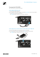
The SL DI 4 XLR Dante™ interface Product overview and LED indicators – front panel 1 P48 LEDs indicate, for each individual XLR input (IN 1, IN 2, IN 3, IN 4), whether the phantom power is activated 2 +45, +30, +15 LEDs indicate the gain settings for each XLR input 3 PAD LEDs indicate, for each individual XLR input, whether the -12 dB pad function is activated 4 POWER LED lights up when the power supply is active Product overview and connections – rear panel IN 4 IN 3 IN 2 IN 1 OUT DC IN 12V 5
The SL DI 4 XLR Dante™ interface Powering the SL DI 4 XLR There are two options to power the SL DI 4 XLR. Power supply via Ethernet cable To power the SL DI 4 XLR via Ethernet: Use an Ethernet cable (CAT-5 or higher) to connect the POE + DATA socket of the SL DI 4 XLR to a PoE port of a PoE-enabled network device. The POWER LED lights up when the power supply is established.
The SL DI 4 XLR Dante™ interface Daisy-chaining the power supply The PWR LINK IN and OUT terminals allow you to daisy-chain the power supply to additional devices. The number of devices that can be daisy-chained is limited. • NT 12-50CS power supply -> maximum of 3 devices. • Power over Ethernet -> maximum of 2 devices WARNING! DANGER OF INJURY DUE TO MISSING OVERLOAD PROTECTION! IF THE DAISY-CHAINING OF THE POWER SUPPLY IS NOT DONE PROPERLY, THIS MAY CAUSE INJURY DUE TO ELECTRIC SHOCK.
The SL DI 4 XLR Dante™ interface Configuring the SL DI 4 XLR using the SL DI CONTROL software All settings of the input and outputs of the SL DI 4 XLR are adjusted using the SL DI CONTROL software. You can download the software at www.sennheiser.com on the product page for the SL DI 4 XLR or in the global download area on the Sennheiser website at www.sennheiser.com/download. Install the software on a network-enabled Windows PC.
The SL DI 4 XLR Dante™ interface Establishing a connection to a SL DI 4 XLR To establish a connection to a SL DI 4 XLR: Select the desired SL DI 4 XLR from the drop-down list on the right of the navigation bar.. The drop-down list shows all SL DI 4 XLR devices that are in the same network as the PC on which the SL DI CONTROL software is running. After having selected the desired device, click on Connect.
The SL DI 4 XLR Dante™ interface Saving and loading settings You can save the settings made as presets or as files. To save the settings: Click on the folder icon on the left of the navigation bar. The following dialog box opens. To save the settings as a preset: From the drop-down list in the Device Preset box, select a preset to which you want to save the settings. The settings can be saved in 10 presets. Click Save to Device.
The SL DI 4 XLR Dante™ interface Identifying devices If you are using several SL DI 4 XLR devices and want to know which device in the software corresponds to which hardware in your installation, you can use the Identify function. Tick the Identify check box at the right of the navigation bar. All four PAD LEDs flash on the corresponding SL DI 4 XLR. The Dante Debug Mode In Dante Debug Mode, the LEDs at the front of the SL DI 4 XLR indicate the diagnostic status.
The SL DI 4 XLR Dante™ interface At the front of the SL DI 4 XLR, the PAD and +15 LEDs of the IN 1, IN 3 and IN 4 inputs indicate the following status information: IN 1 input: SYNC IN 4 IN 3 IN 2 The PAD and the +15 LED of the IN 1 input light up:: PTP is being synchronized.
The SL DI 4 XLR Dante™ interface Eingang IN 3: ERR IN 4 IN 3 IN 2 IN 1 +15 The PAD and +15 LEDs of the IN 3 input light up: Capability is corrupted The +15 LED of the IN 3 input lights up: Memory Stack Overflow The +15 LED of the IN 4 input lights up: System starts up The PAD LED of the IN 4 input lights up: System is ready for operation PAD IN 4 IN 3 IN 2 IN 1 +15 PAD Eingang IN 4: SYS IN 4 IN 3 IN 2 IN 1 +15 PAD IN 4 IN 3 IN 2 IN 1 +15 PAD SL DI 4 XLR 11/11