TeamConnect Ceiling 2 Instruction manual Sennheiser electronic GmbH & Co. KG Am Labor 1, 30900 Wedemark, Germany, www.sennheiser.com Publ.
FR Important safety instructions . . . . . . . . . . . . . . . . . . . . . . . . . . . . . . . . . . . . . . . . . . . . . . . . . . 20 Intended use . . . . . . . . . . . . . . . . . . . . . . . . . . . . . . . . . . . . . . . . . . . . . . . . . . . . . . . . . . . . . . 20 Safety instructions for installation . . . . . . . . . . . . . . . . . . . . . . . . . . . .
Important safety instructions Important safety instructions 1. Read these safety instructions and the instruction manual of the product. 2. Keep these safety instructions and the instruction manual of the product. Always include all instructions when passing the product on to third parties. 3. Always include this instruction manual and the safety guide when passing the product on to third parties. 4. Only use attachments, accessories and spare parts specified by the manufacturer. 5.
Package contents Package contents TeamConnect Ceiling 2 • 3-pin Phoenix connector (3.81) • 8 self-adhesive rubber feet • 2 eye bolts (M4x10) • Instruction manual • Supplement sheet with manufacturer declarations DE • SL CM EB US SL CM EB 625 Ceiling mounting frame Angle brackets (for 2 ft ceiling grid) Angle brackets (for 625 mm ceiling grid) FR SL CM FB EN Accessories 6.4 mm M4x12 M3x8 Torx10 M3x8 Torx10 Art. no.
Connectors and controls Connectors and controls Primary Secondary 4 4 Analog Out + - Reset 5 Reset button Supports redundancy and switched mode To restore the factory settings Analog audio output Hold for 5 seconds 3-pin socket • 7 7 Dante™ interface with two RJ-45 sockets, Primary and Secondary Digital audio output • 6 PoE/Ctrl 6 • 5 Ethernet PoE/Ctrl socket Suitable for Phoenix Contact MCVW 1.5-3-ST-3.
Connecting the TeamConnect Ceiling 2 Outputting analog audio signals Use the Analog Out socket to output analog audio signals. Variant 1: output analog audio signal to a DSP. DE TeamConnect Ceiling 2 Analog analoges audio cable* Audiokabel* IT FR EN - ES DSP Variant 2: output analog audio signal to video conference codec.
Connecting the TeamConnect Ceiling 2 Outputting digital audio signals The Dante™ interface with two RJ-45 sockets, Primary and Secondary, is used for outputting digital audio signals. The interface supports redundant output and series connection of multiple ceiling microphones (switched mode). The mode is configured using the Dante Domain Manager or Dante Controller from Audinate (www.audinate.com).
Planning the installation Planning the installation Possible installation variants Variant 2: Variant 3: installed flush in a dropped/coffered ceiling mounted directly below the ceiling suspended from the ceiling Accessories required: Accessories required: Accessories required: SL CM EB US (590 mm to 2 ft) or SL CM EB 625 (590 mm to 625 mm) SL CM FB SL CM SK Ceiling mounting frame Ceiling suspension set See „Accessories“ on page 21 See „Accessories“ on page 21 Angle brackets See „Accessories
Installing the TeamConnect Ceiling 2 Installing the TeamConnect Ceiling 2 Variant 1: installed flush in a dropped/coffered ceiling The TeamConnect Ceiling 2 can be easily installed in a dropped ceiling or coffered ceiling with square ceiling tiles (600 x 600 mm). Angle brackets are available for ceiling tiles with the standard dimensions of 2 ft or 625 mm. When flush mounting, do not install the TeamConnect Ceiling 2 directly next to lights or other electrical devices in the ceiling.
Installing the TeamConnect Ceiling 2 DE Installing the TeamConnect Ceiling 2 in the ceiling without angle brackets (600 x 600 mm grid) EN 590 mm FR 5 - 10 mm 5 - 10 mm IT f Remove a tile from the ceiling. f Place the TeamConnect Ceiling 2 in the frame in the coffered ceiling. Installing the TeamConnect Ceiling 2 in the ceiling with angle brackets (2 x 2 ft or 625 x 625 mm grid) 4x SL CM EB US M3x8 4x SL CM EB 625 f Attach the angle brackets to the TeamConnect Ceiling 2 as shown in the figure.
Installing the TeamConnect Ceiling 2 Mounting with SL CM EB 625: 618 mm 5 - 10 mm 5 - 10 mm f Remove a tile from the ceiling. f Place the TeamConnect Ceiling 2 in the frame in the coffered ceiling. f Maintain the distances indicated in the figures. Variant 2: mounted directly below the ceiling M4x8 To mount the product directly below the ceiling, you need the SL CM FB ceiling mounting frame. Screws and anchors for mounting the product to the ceiling are not included with delivery.
Installing the TeamConnect Ceiling 2 EN DE Fastening the angle brackets to the TeamConnect Ceiling 2 M4x12 PT ES IT FR M4x8 f As shown in the figure, fasten the four angle brackets to the TeamConnect Ceiling 2 using two of the included M4x8 screws for each bracket. f Screw one M4x12 screw into each of the four angle brackets from the side. f Do not screw the screw all the way in (see figure).
Installing the TeamConnect Ceiling 2 Preparing the ceiling fastener 1 A C B B f Unscrew part A of the ceiling fastener from part B. f Thread the steel cable C into part B so that the ball on the steel cable is in part B. f Repeat these steps for the other three fasteners. Mounting the ceiling fastener f Attach part A of the ceiling fastener to the ceiling using a suitable anchor and screw. f Use the included drilling template to align the drill holes.
Installing the TeamConnect Ceiling 2 Mounting the TeamConnect Ceiling 2 on a VESA mount ES IT FR EN DE The SL CM VB VESA adapter (available separately) allows you to mount the TeamConnect Ceiling 2 on any 100 x 100 mm or 200 x 200 mm VESA mount. f Fasten the ceiling mount to the ceiling using suitable screws and anchors. PT f Observe the mounting specifications from the manufacturer.
Configuring the TeamConnect Ceiling 2 Configuring the TeamConnect Ceiling 2 Downloading Sennheiser Control Cockpit To configure and use the TeamConnect Ceiling 2, you need the free Sennheiser Control Cockpit control software. You can download it here: www.sennheiser.com/control-cockpit-software To use the Sennheiser Control Cockpit, you must complete a one-time registration with your e-mail address to receive the software activation code.
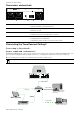
Configuring the TeamConnect Ceiling 2 Variant 2: configuring the TeamConnect Ceiling 2 as a standalone solution using a computer Proceed as follows to configure the TeamConnect Ceiling 2 without network integration using a computer: f Connect the computer to a PoE-capable network switch using a network cable (Cat5e or higher). Alternatively, you can use a PoE injector. f Connect the network switch to the Ethernet PoE/Ctrl socket on the TeamConnect Ceiling 2.
Specifications Specifications Product properties Dimensions (L x W x H) 590 x 590 x 43 mm Weight 6 kg (5.5 oz) Audio outputs One 3-pin socket (suitable for Phoenix Contact MCVW 1.5-3-ST-3.81) Two Dante™ Digital Audio Network sockets (RJ-45) Network/Control One RJ-45 Ethernet socket for PoE supply and data/ control Supply voltage PoE IEEE 802.3af Class 3 Power consumption Max. 8.