
Operation Manual


Product overview
6 | XS WIRELESS
Product overview
An overview of the products is given on the inside front cover of this instruction manual.
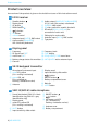
EM 10 receiver
1 Standby button
2 Display panel
3 UP button
4 DOWN button
5 button
6 set button
7 volume control
8 Antenna input (ANT B), BNC socket
9 Audio output (BALANCED),
XLR-3M socket, balanced
0 Audio output (AUDIO OUT UNBALANCED)
¼” (6.3 mm) jack socket, unbalanced
A LINE/MIC slide switch
B SQ rotary switch for squelch threshold
C DC socket (DC 12 V, 300 mA) for
connection of mains unit
D Cable grip for mains cable
E Antenna input (ANT A), BNC socket
F Type plate
Display panel
G Frequency
H RF signal level “RF”
I Audio level “AF”
J Battery charge status of transmitter
K Channel
L Frequency bank
M SYNC display
N SCAN, PRESET, TUNE menu items
O ANT A/ANT B active antenna input
SK 20 bodypack transmitter
1 Microphone/instrument input
2 mute LED, yellow
(lit = muting is activated)
3 power LED, red
(lit = switched on;
flashing = batteries are low)
4 Antenna
5 Display panel
6 Input sensitivity slide switch
7 button
8 ON/OFF button
9 Battery compartment cover
0 Belt clip
A MUTE button
SKM 35/SKM 65 radio microphone
1 Sound inlet basket (SKM 35 = black
identification ring; SKM 65 = grey
identification ring)
2 Display panel
3 mute LED, yellow LED
(lit = muting is activated)
4 MUTE button
5 Input sensitivity slide switch
6 ON/OFF button
7 button
8 LED power, red LED
(lit = switched on;
flashing = batteries are low)
9 Antenna cover
0 Battery compartment
A
B
C
D