
Operating instructions


FC Operation & Maintenance Guide (20 & 25 Amp)
5
Inherent current limited at 100% to 110% of rated output
Temperature compensation
Output voltage changes in accordance with negative temperature coefficient of battery (-
0.12%
per degree F). This maximizes battery performance and life.
Protection
Current limited output; sustains short circuit
Standard AC and DC circuit breakers
Indicators
• DC voltmeter
• DC ammeter
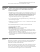
• Alarms (FCA only):
Alarm Indicator FCA model suffix
AC on LED
Low battery voltage LED & form C contact -2231, -2431
Charger failure LED & form C contact -2231, -2431
AC fail LED & form C contact -2431 only
High battery voltage LED & form C contact -2431 only
Delay circuitry in the charger failure, low battery and high battery alarm systems prevents
spurious indications
Controls & adjustments
• Separate adjustments for float & boost voltages
• Separate adjustments for low and high DC alarms (FCA only)
• Optional boost timer (0-24 hours or 0-72 hours)
Ambient
Operates without de-rating from -10C to +50C. Humidity 5% to 95%, non-condensing.
Natural convection cooled.
3
Installation
3.1 Mounting (for dimensions, refer to drawings at end of manual)
Mount on a clean, dry, fixed wall which is protected from extremes of temperature. Allow at least 6
inches above and below the unit, and three inches either side for proper ventilation. The unit must be
mounted vertically.
Mounting screw size should be #10 minimum.
If the charger must be mounted on or in a vibrating enclosure, the mounting arrangement should be
designed to provide full vibration isolation.
Long battery cable runs, while not generally acceptable, are not a problem with the FC series
charger. SENS True Voltage Sensing circuit automatically compensates for voltage drop in the
charging leads.