SENSAPHONE ® REMOTE MONITORING SOLUTIONS Wireless Sensor Gateway WSG30 USER’S MANUAL Version 1.
WSG30 Users Manual Every effort has been made to ensure that the information in this document is complete, accurate and up-to-date. Sensaphone assumes no responsibility for the results of errors beyond its control. Sensaphone also cannot guarantee that changes in equipment made by other manufacturers, and referred to in this manual, will not affect the applicability of the information in this manual. Copyright © 2012 by SENSAPHONE® First Edition, version 1.
1 Year Limited Warranty PLEASE READ THIS WARRANTY CAREFULLY BEFORE USING THE PRODUCT. THIS LIMITED WARRANTY CONTAINS SENSAPHONE’S STANDARD TERMS AND CONDITIONS. WHERE PERMITTED BY THE APPLICABLE LAW, BY KEEPING YOUR SENSAPHONE PRODUCT BEYOND THIRTY (30) DAYS AFTER THE DATE OF DELIVERY, YOU FULLY ACCEPT THE TERMS AND CONDITIONS SET FORTH IN THIS LIMITED WARRANTY.
WSG30 Users Manual LOSS OF BUSINESS, LOSS OF DATA OR INFORMATION, OR FINANCIAL LOSS, FOR CLAIMS OF ANY NATURE, INCLUDING BUT NOT LIMITED TO CLAIMS IN CONTRACT, BREACH OF WARRANTY OR TORT, AND WHETHER OR NOT CAUSED BY WARRANTORS’ NEGLIGENCE.
the Uniform Commercial Code as adopted by the State of Delaware shall apply. 4. PROCEDURE FOR OBTAINING PERFORMANCE OF WARRANTY: In the event that the Product does not conform to this warranty, the Product should be shipped or delivered freight prepaid to a Warrantor with evidence of original purchase. 5.
WSG30 Users Manual Table of Contents FCC Requirements . . . . . . . . . . . . . . . . . . . . . . . . . . . . . . . . . . . . . . . . . . . . . . . . . . . . . . . . . . . . . . . . . . . . II RF Exposure. . . . . . . . . . . . . . . . . . . . . . . . . . . . . . . . . . . . . . . . . . . . . . . . . . . . . . . . . . . . . . . . . . . . . . . . . .
Admin. . . . . . . . . . . . . . . . . . . . . . . . . . . . . . . . . . . . . . . . . . . . . . . . . . . . . . . . . . . . . . . . . . . . . . . . . . . . . . . Sensor Programming . . . . . . . . . . . . . . . . . . . . . . . . . . . . . . . . . . . . . . . . . . . . . . . . . . . . . . . . . . . . . . . . . . Datalogging Capacity . . . . . . . . . . .
WSG30 Users Manual Chapter 1: Introduction Congratulations on your purchase of the Sensaphone WSG30. This device can work with up to 30 Wireless sensors to monitor Temperature, Humidity, Water on the floor, Power, Dry Contacts, and 4-20mA signals. The sensors use mesh networking technology to create multiple communication paths between the sensors and the WSG30 to ensure reliable communications. Sensors can also be battery powered for those installations where an outlet may not be available.
Chapter 2: Installation ChAptER 2: iNStALLAtioN phYSiCAL dESCRiptioN The WSG30 is housed in a plastic 7.6”w x 5.1”h x 2.0”d enclosure and is suitable for wall mounting. dEvICE layout The front panel contains an 80 character LCD and a push button keypad. The top of the unit has an antenna connector and the bottom contains the power and Ethernet connections.
WSG30 Users Manual RJ-45 10/100BASE-T Ethernet Port This jack is for connecting to your network. Two LEDs indicate Link Status (green) and Receive Data status (yellow). Power Jack Attach the 9VDC power supply to the power jack. The device will power up as soon as power is applied. Backup Battery The device contains a built-in 6V 1.3AH rechargeable battery. The system will monitor the condition of the battery and an alarm can be initiated if the battery gets low.
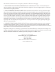
Chapter 2: Installation SENSAPHONE® REMOTE MONITORING SYSTEM WSG30 WIRELESS SENSOR GATEWAY 6.750 MENU UP DOWN ENTER 3.5 Figure 2: Wall-mounted WSG30 Unit tuRnIng oFF thE wsg30 Once the power supply is plugged-in the WSG30 will power up. If power is subsequently removed, the internal battery will continue to power the device. If you wish to turn off the device completely, you must enter the Power Down command at the keypad and then unplug the power supply. See steps below: 1) Press Menu.
WSG30 Users Manual Chapter 3: Network Configuration The WSG30 is designed for installation on an Ethernet network. This involves assigning it an IP address. By default the unit will try to acquire an IP address automatically using DHCP. If it is successful you can then use the LCD and keypad to determine the IP address and then assign it a fixed IP address. If no DHCP server is found the unit will fallback to a fixed IP address of 192.168.1.250.
Chapter 3: Network Configuration Network Setup using your Computer There are three additional methods listed below to configure the network settings in the WSG30 . These all assume that you do not have a DHCP server and, as a result, the WSG30 has configured itself to the default address of 192.168.1.250. Note that all three options below require you to modify the Network settings on your computer. Method 1 Using a RJ45 crossover cable connect your PC to the device.
WSG30 Users Manual Chapter 4: Configuring Wireless Sensors The WSG30 allows you to configure up to 30 wireless sensors. Sensors are available to monitor a variety of environmental conditions - see Appendix B for a complete list. A successful installation will require some planning to make sure everything will work smoothly. The WSG30 and sensors utilize mesh networking technology to ensure reliable wireless communications, but this requires that you follow a few rules during the setup process.
Chapter 4: Configuring Wireless Sensors Example 2 - Eight to Fifteen Sensors At least one sensor will have to be configured as a router. The router should be located mid-way between the farthest sensor and the WSG30. The routing sensor should be added to the system first.
WSG30 Users Manual Example 4 - Twenty Four to Thirty Sensors At least three sensors will have to be configured as routers. The routers should be located an equal distance between the farthest sensor and the WSG30, and centrally located to minimize the distance between sensors in the general area of the router and the WSG30. The routing sensors should be added to the system first.
Chapter 4: Configuring Wireless Sensors Click Save when finished. Next, insert batteries into the sensor and connect a power supply (if required). A power supply is required if the sensor is configured to be a Router. A power supply is optional if configured as an End Point. Monitor the Summary or Sensors screen to confirm that the sensor has connected. Notes about Sensor Programming In end-point mode the sensor consumes minimal power, which allows it to run on batteries.
WSG30 Users Manual Chapter 5: Programming Introduction The WSG30 is completely programmable from the internal webpage. This makes it easy to setup, program, and utilize the features of the device. The web page can be accessed by opening your internet browser (Internet Explorer, Firefox, Safari, …) and entering the IP address of your WSG30 (see the Network Configuration section in Chapter 1 for assistance).
Chapter 5: Programming and on e-mail alarm messages. The Unit Name will appear on SMS text messages. Use these fields to help identify the facility and/or location so that when alarms happen you’ll know exactly where the trouble occurred. This screen also provides an entry for a Time Server using the Time Protocol (TP) format on port 37. This is used to periodically synchronize the system clock to keep it accurate. It is recommended that you keep this set to the default setting (i.e. time.sensaphone.com).
WSG30 Users Manual parameters is provided along with the ability to send traps when alarms occur. A complete SNMPv1 MIB is provided on the WSG30 CD. Fig 4: SNMP setup screen Common OIDs for Sensor Values Sensor 1 Value .1.3.6.1.4.1.8338.1.1.4.1.1.1.1.48 Sensor 2 Value .1.3.6.1.4.1.8338.1.1.4.1.1.1.2.48 Sensor 3 Value .1.3.6.1.4.1.8338.1.1.4.1.1.1.3.48 Modbus® The WSG30 can be accessed via Modbus®TCP protocol and function as a slave device.
Chapter 5: Programming Network The Network Settings page allows you to view and configure all parameters associated with accessing the device via the Ethernet port (see Network Configuration in chapter 1 for details). This screen also displays the device’s MAC address and lets you configure the web page port number. Note that if you change the port number to anything other than 80 (default) you will be required to enter the port number as part of the device address in your browser (e.g xxx.xxx.xxx.
WSG30 Users Manual Fig 7: Admin setup screen Sensor Programming This section explains how to program the Sensor parameters for monitoring, alarming, and data logging based on your requirements. The WSG30 features numerous settings for customizing the operation of the device. To begin, click on any sensor listed in the table on the Summary or Sensor screens.
Chapter 5: Programming The Sensor Edit page shows all of the parameters that can be programmed for the selected sensor. The definitions below explain how each parameter functions. Sensor Enable/Disable: This setting determines if the Sensor is being used (Enabled) or not (Disabled). Selecting Disabled will remove it from the summary screen and prevent alarms from occurring. It will, however, maintain its wireless connection.
WSG30 Users Manual Fig 9: Sensor schedule screen Profile Selection: This setting determines which User(s) get contacted when the sensor goes into alarm. Alarm Reset Enable/Disable: This setting enables or disables the Alarm Reset Feature. The Alarm Reset feature is used to re-send alarm messages in the event that a fault condition is not corrected in a timely fashion.
Chapter 5: Programming Datalogging Capacity The datalogging capacity of the WSG30 varies depending on how many sensors you’re logging and what the logging interval is for each. Memory is maximized if the logging interval for each sensor is in multiples of each other. For example, if sensor 1 is set to 1 minute and sensor 2 is set to 5 minutes, you’ll get better memory usage than if sensor 1 were set to 1 minute and sensor 2 was set to 2.5 minutes.
WSG30 Users Manual Escalation Priority: This can be set to any number between 1 and 8. Profiles set to escalation level 1 will immediately receive alarm messages. Those set to higher escalation levels will have their alarm messages delayed by the time entered for the Escalation Delay on the System Setup screen. If the alarm condition resets or corrects itself before the Escalation delay expires then no message(s) will be sent to those users with a higher escalation setting.
Chapter 6: History Chapter 6: History This chapter explains how to query the Event and Data Log History. The Event Log is a time-stamped list of system events such as System Startup, Alarm Detection, Message Delivery, … The Data Log contains time stamped records of the input values. The logging rate is configured on the Sensor programming screen for each input.
WSG30 Users Manual ChAptER 7: WiRELESS SENSoRS WSg WiRELESS tEMpERAtURE SENSoR INTRODUCTION The WSG Wireless Temperature sensor provides remote temperature monitoring without running wires. Temperature data is sent from the sensor to the WSG30 via an integrated 2.4GHz Wireless radio. The device can transmit its signal up to 300’ indoors and even greater distances when it has line-of-site.
Chapter 7: Wireless Sensors Battery Installation Carefully separate the top of the enclosure from the bottom. Locate the battery holder on the circuit board. Take note of the polarity markings identifying the positive and negative ends of the batteries. Install the batteries. Re-attach the top and cover. Power supply Wiring (Router Mode) When using your wireless sensor in Router mode, you must use an external power supply (Sensaphone Part #XFR-0041).
WSG30 Users Manual WSg WiRELESS hUMiditY SENSoR INTRODUCTION The WSG Wireless Humidity sensor provides remote monitoring without running wires. Data is sent from the sensor to the WSG30 via an integrated 2.4GHz Wireless radio. The device can transmit its signal up to 300’ indoors and even greater distances when it has line-of-site.
Chapter 7: Wireless Sensors Power supply Wiring (Router Mode) When using your wireless sensor in Router mode, you must use an external power supply (Sensaphone Part #XFR-0041). This is required because router mode uses more power than can be supplied by batteries alone for an extended period of time. You can also use a power supply when the sensor is configured as an End Point, which will greatly extend the life of the batteries and minimize the need to change them.
WSG30 Users Manual WSg WiRELESS dRY CoNtACt SENSoR INTRODUCTION The WSG Wireless Dry Contact sensor provides remote monitoring without running wires. Contact data is sent from the sensor to the WSG30 via an integrated 2.4GHz Wireless radio. The device can transmit its signal up to 300’ indoors and even greater distances when it has line-of-site.
Chapter 7: Wireless Sensors Power supply Wiring (Router Mode) When using your wireless sensor in Router mode, you must use an external power supply (Sensaphone Part #XFR-0041). This is required because router mode uses more power than can be supplied by batteries alone for an extended period of time. You can also use a power supply when the sensor is configured as an End Point, which will greatly extend the life of the batteries and minimize the need to change them.
WSG30 Users Manual SPECIFICATIONS Operating Temperature Range: 32° to 122° F (0° to 50° C) Operating Humidity: 5- 90% RH non-condensing Range (Indoor/Urban): Up to 250’ (76m) Transmit Power Output: 100mW (20dBm) Operating Frequency: ISM 2.4 GHz Power: (2) AA alkaline batteries and/or 5VDC (300mA) plug-in adapter Battery Life: Up to 2 years @ sampling interval = 3 seconds Dimensions: 3.1” x 3.8” x 1.1” (7.9cm x 9.8cm x 2.
Chapter 7: Wireless Sensors WSg WiRELESS poWER SENSoR INTRODUCTION The WSG Wireless Power sensor provides remote power monitoring without running wires. Power status is sent from the sensor to the WSG30 via an integrated 2.4GHz Wireless radio. The device can transmit its signal up to 300’ indoors and even greater distances when it has line-of-site.
WSG30 Users Manual Power supply Wiring To connect the power supply, remove the sensor cover and locate the screw terminals labeled “5V DC”. connect the positive wire from the power supply to the “+” terminal. Plug the power supply into an appropriate outlet. MOUNTING The sensor can be mounted directly on a flat surface. Consideration should be given as to whether or not an electrical outlet will be required if using the optional power supply.
Chapter 7: Wireless Sensors WSG Wireless 4-20mA sensor INTRODUCTION The WSG Wireless 4-20mA sensor provides remote monitoring of 4-20mA transducers without running wires. Contact data is sent from the sensor to the WSG30 via an integrated 2.4GHz Wireless radio. The device can transmit its signal up to 300’ indoors and even greater distances when it has line-of-site.
WSG30 Users Manual 24 VDC Power Supply The Wireless 4-20mA sensor has a internal 24 VDC power supply that is intended to be used to power your 4-20mA transducer. It can provide up to 30mA of current. If your transducer does not require an external power supply then you can disable the 24V supply in the sensor by moving the 24VDC jumper on the circuit board to the OFF position. This will conserve battery power in the event of a power failure. off . . .
Chapter 7: Wireless Sensors SENSAPHONE® REMOTE MONITORING SYSTEM WIRELESS SENSOR GATEWAY 4-20mA SENSOR Self–Powered 4-20mA Transducer 5VDC GND|mA|24VDC 4-20mA Output + – Ground 4-20mA sensor with self–powered transducer Battery Installation Remove the four screws on the bottom of the enclosure. Carefully separate the top of the enclosure from the bottom. Locate the three battery clips on the circuit board.
WSG30 Users Manual Software Configuration The Wireless 4-20mA sensor can provide a scaled value to match the calibrated range of your transducer. In the WSG30 web page, open the Sensor Edit screen for the Wireless 4-20mA Bridge sensor. Insert the Low (4mA) and High (20mA) values for your transducer into the Table Low and Table High fields. The WSG30 will display the scaled value. You may wish to include the units of measure in the Units field.
Chapter 7: Wireless Sensors WSG Wireless spot water detection sensor INTRODUCTION The WSG Wireless Spot Water Detection sensor provides remote leak detection monitoring without running wires. Contact data is sent from the sensor to the WSG30 via an integrated 2.4GHz Wireless radio. The device can transmit its signal up to 300’ indoors and even greater distances when it has line-of-site.
WSG30 Users Manual + – + + – – Proper battery installation SPECIFICATIONS Operating Temperature Range: 32° to 122° F (0° to 50° C) Operating Humidity: 5- 90% RH non-condensing Range (Indoor/Urban): Up to 250’ (76m) Transmit Power Output: 100mW (20dBm) Operating Frequency: ISM 2.4 GHz Power: (3) AA alkaline batteries Battery Life: Up to 2 years @ Sampling frequency = 3 seconds Dimensions: 6.8” x 3.5” x 1.
Chapter 7: Wireless Sensors WSG Wireless Zone Water detection sensor INTRODUCTION The WSG Wireless Zone Water Detection sensor provides remote leak detection without running wires. Contact data is sent from the sensor to the WSG30 via an integrated 2.4GHz Wireless radio. The device can transmit its signal up to 300’ indoors and even greater distances when it has line-of-site.
WSG30 Users Manual – – + + – + Proper battery installation Power supply Wiring (Router Mode) When using your wireless sensor in Router mode, you must use an external power supply (Sensaphone Part #XFR-0046). This is required because router mode uses more power than can be supplied by batteries alone for an extended period of time. You can also use a power supply when the sensor is configured as an End Point, which will greatly extend the life of the batteries and minimize the need to change them.
Chapter 7: Wireless Sensors Battery Life: Up to 2 years @ sampling interval = 3 seconds Dimensions: 6.8” x 3.5” x 1.
WSG30 Users Manual Appendix A: Weekly Testing Procedure We recommend that you test your WSG30 system weekly to be sure it is functioning properly. This will ensure that when a problem arises the WSG30 will be ready to alert the appropriate personnel. A test log template is included at the back of this manual. There are several tests that can be performed: 1) Check the status of all monitored conditions on the WSG30 by viewing the web page.
Appendix B: WSG30 Accessories Appendix B: WSG30 Accessories The sensors listed below are available from Sensaphone and represent the most commonly used input devices. Other sensors, designed for more specialized applications, may also be used. Commercial or industrial electrical supply houses can provide devices to monitor virtually any condition. For further information, contact Sensaphone Customer Service at (610)558-2700. PART # . . . . . . . . . . . . DESCRIPTION FGD-WSG30-TMP. . . . .
WSG30 Users Manual Appendix C: Returning a WSG Device for Repair In the event that any of your Sensaphone WSG30 devices do not function properly, we suggest that you do the following: 1) Record your observations regarding the individual unit’s malfunction. 2) Call the Technical Service Department at 610.558.2700 prior to sending the unit to Sensaphone for repair. If the unit must be sent to Sensaphone for Servicing, please do the following: 1) Power the device off.
Appendix D: Specifications Appendix D: Specifications Alarm notification methods: • E-Mail, Text Message, SNMP Trap Certification Standards: • FCC Part 15 – Class B Compliant Data logging • 8 Alarm escalation levels • 32,000 Samples (all samples include data, date, and time) • Comprehensive scheduling per input, user, and alarm destination Destinations: • 8 Programmable User Profiles • 4 Programmable destinations per profile • Alarms can be assigned to specific User Profiles Communication types: • E-Ma
WSG30 Users Manual Appendix C: Modbus® specifications Inputs VALID RANGE BASE OFFSET 169 Input Calibration (fixed-point integer) sint16 ±300.00 4x10496 Normal Logging Frequency (max 31 days) uint32 0 - 2678400 s. 4x10500 Alarm Logging Frequency (max 31 days) uint32 0 - 2678400 s. 4x10502 Alarm low limits float ±80000.00 4x10583 Alarm high limits float ±80000.00 4x10585 Low table limit (4-20mA) float ±80000.00 4x10587 High table limit (4-20mA) float ±80000.
Appendix C: Modbus® specifications Enable/Disable Profile bit TRUE or FALSE 0x00512 10 CONTACTS TYPE VALID RANGE BASE OFFSET e-mail address string 0 - 64 characters 4x02144 87 Type of communication (voice, e-mail, SMS) uint8 0-5 4x02180 42-byte array Any Value 4x02206 bit TRUE or FALSE 0x00768 TYPE VALID RANGE BASE DNS Server IP Address uint32 Any Value 3x00000 Gateway IP Address uint32 Any Value 3x00002 IP Address uint32 Any Value 3x00004 Netmask uint32 Any Value
WSG30 Users Manual Modbus® Notes Modbus® Addresses Address Ranges The Modbus® address ranges are laid out according to the following color-coded table. The format below is TxDDDDD where “T” is the address type (bit/word, readwrite/read-only) and DDDDD is a 5 digit decimal base number from 0 to 65535.
Appendix C: Modbus® specifications Quick Access Table The following is a quick access table to retrieve the wordaccess, read-only current input values as human-readable ASCII strings. Use the Modbus® command “4” to access the data.
WSG30 Users Manual be terminated by a “0” because it is less than 32-characters long, but not a name that is 32-characters long. Arrays are never terminated. Non-generic data Timestamps Timestamps can be decoded using the following equations. “div” means integer division where the remainder is dropped. “mod” means the “modulus” or “remainder”. All values start at “0”. For example, Day 0 is the first day of the month and Month 0 is January. The year is offset by -2000, so that a value of 9 indicates 2009.
Appendix C: Modbus® specifications Access Level: Access Level 0 1 2 Description Access Disabled Read-Only Read-Write Contact Types: Contact Type 3 9 Description Email or SMS SNMP Trap Modbus® Configuration: Operating Mode 0 1 2 Bit Representation 0 1 2 Description Modbus® Disabled Read-Only Read-Write Description Big-Endian Byte Order Little-Endian Word Order (Modbus® Default) Big-Endian Byte Order Big-Endian Word Order (Network Byte Order) Little-Endian Byte Order Little-Endian Word Order (Intel By
WSG30 Users Manual Test Log 56
Test Log 57