
Product Info


Page 3
LAYOUT CONSIDERATIONS
Improper placement of planes, traces or components will result in antenna nulls
or complete detuning. First, the area under the antenna on all board layers
should be completely free of components, traces, or groundplane. In addition,
no components or traces should pass within .25" of the top, sides, front or back
of the antenna. Ideally the antenna will be mounted at the top of the board and
given an unobstructed field of view in all directions. Components placed in the
area below the back edge of the antenna will have little effect since the antenna
has a null at its back edge when referenced appropriately to groundplane.
Components placed to the sides or top of the antenna or items such as
displays mounted in proximity to the antenna will produce nulls and, possibly,
detuning. The antenna may be referenced to groundplanes of all different
surface areas; however, it has been optimized for a 1.5"x 3" plane area. The
best performance and lowest VSWR will be obtained when referenced to a
plane of similar area.
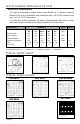
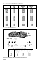
The recommended pad layout is illustrated below. The top layer of the board
generally has the antenna mounting pads and feed trace. The ground pads are
connected to the groundplane layer through vias. Use care in the sizing and
placement of the vias to prevent solder migration from the attachment pads
during attachment.
Pads and outline shown
for groundplane
position reference only.
Top Layer
Bottom Layer
Vias To
Groundplane
0.100"
0.090"
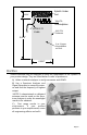
FEED CONSIDERATIONS
Like most reduced-size antennas the “Splatch” has a fairly high Q and thus
exhibits narrow bandwidth characteristics.The single most critical element in
insuring the optimum function of the “Splatch” is to minimize the length of the
feed trace (Transmission Line) to the “Splatch” itself.The feed trace should be
less than .25" and in all cases microstripped. The term “Microstrip” refers to
a trace passed over groundplane of a width appropriate to create a 50-ohm
transmission line between the module and the antenna. Since the antenna
does not present a true and stable 50-ohm match, the feed trace tends to
lower the antenna’s resonant frequency. Given the antenna’s narrow
bandwidth, it can easily be detuned by the length of the feed trace; thus, the
trace should be kept as short as possible. Additional microstrip details are
available in the reference section of this guide