
User Manual


6
Initialization: These pins are digital inputs and outputs used during the initialization of the module.
Two-wire interface: Both SDA and SCK have 10K ohm pull-ups to VCC. The module acts as the master on
the bus.
UART: Two wire (RX/TX) or four wire (RX/TX/CTS/RTS) logic level interface. Runs at 9600 baud, 8 data
bits, no parity, 1 stop bit.
Reset: An active low signal (RESET#) to reset the microcontroller. Used during debug and test of the module.
JTAG Programming: These provide a four wire interface into JTAG controller on the modules
microcontroller. These are used during debug and test of the module.
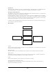
Mechanical interface
(all dimensions in inches unless otherwise noted)
Top side module height: max 0.250”
Bottom side module height: max 0.169”
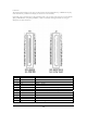
The OEM100 is a printed circuit board (PCB) assembly with two connectors (P3 and P5) and three mounting
holes. The primary interconnection is P3, the 41 position board to board, connector on the bottom of the
assembly. When loaded into its mating connector on a carrier board, the bottom of the OEM100’s PCB will
be 4.3mm (0.169 inches) from the top of that carrier board. The mounting holes are designed to accommodate
4mm tall, board to board, plastic, stacking posts also on the bottom side (e.g. Richco p/n MDLSP1-04M-01).
Alternatively, #2, nylon fasteners may be used.