
User Manual


8
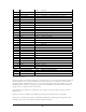
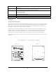
Battery life Up to 3 years with a 2/3A Lithium battery using a 2 minute report interval (sensor
dependent)
Range Up to 1000’ (outdoors, line of sight) (1 mile OEM1000)
Up to 300’ (typical indoor conditions) (1000 feet OEM1000)
Connector options Two (2) analog input lines
Six (6) digital I/O lines
Two wire interface bus
UART (TX, RX, RTS and CTS)
Duty cycle Remotely user-adjustable (default 3 minutes)
Antenna Board mounted, omni-directional antenna included
LEDs 3 diagnostic LEDs (red, yellow and green)
Appendix A
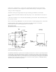
Developer’s Kit Adapter Board
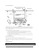
Optionally a Sensicast Developer’s Kit Adapter Board (P/N 1408) can be used as to ease prototyping with the
OEM module. There are four .104” diameter mounting holes that correspond to the mounting holes of the
OEM module. The board has a Hirose receptacle that mates with the OEM module’s 41 position header.
Each signal is brought to a test point arranged on a 2mm grid.
Some of the more commonly used signals are brought to three other connectors (P1, P2 and P3) for ease of
integration with a microcontroller based target board. A multicolor ribbon cable the mates with P1 is also
provided. There is a 3.3V regulator that allows the user to power the OEM module from an AC power
adapter. Here is a drawing of the adapter board and a description of the connectors and their signals
If the optional target developer’s board is being used, the I2C and jumper wires included are compatible with
P2 and P3.