
User Manual


9
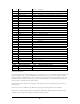
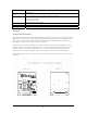
P1 - 10 position (2x5) 0.1 inch pitch ribbon cable connector
pin signal description Ribbon cable color
1 INT_S2R Interrupt line from sensor to radio module, active on rising edge Brown
2 INT_R2S Interrupt line from radio module to sensor, active on rising edge Red
3 SCL Two wire interface, serial clock Orange
4 SDA Two wire interface, serial data Yellow
5 TXD UART (3V logic level), radio module transmit data Green
6 RXD UART (3V logic level), radio module receive data Blue
7 RTS UART (3V logic level), radio module ready to send Violet
8 CTS UART (3V logic level), radio module clear to send Gray
9 EXT_VCC Power source for radio module (2.0V to 3.6V) White
10 GND Ground Black
P2 – 2 position 0.1 inch pitch header
pin signal description
1 INT_S2R Interrupt line from sensor to radio module, active on rising edge
2 INT_R2S Interrupt line from radio module to sensor, active on rising edge
P3 - 4 position (2x2) 0.1 inch pitch ribbon cable connector
pin signal description
1 SCL Two wire interface, serial clock
2 SDA Two wire interface, serial data
3 EXT_VCC Power source for radio module (2.0V to 3.6V)
4 GND Ground
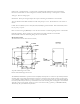
P4 - 3 position 0.1 inch pitch jumper
Short pins Function
1 and 2 Power from on board 3.3V regulator
2 and 3 Power from P1 or P3
P5 – barrel connector jack
Outer ground
Center +5V
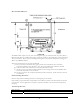
P6 - 41 position Hirose DF9 receptacle (bottom) See above description of signals