302-066 Installation & Operating Instructions Series 3100 Differential Pressure Transmitter SUPERSEDES: April 1, 2012 EFFECTIVE: August 1, 2012
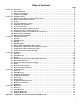
Table of Contents Page Section 1.0 Introduction . . . . . . . . . . . . . . . . . . . . . . . . . . . . . . . . . . . . . . . . . . . . . . . . . . . . . . . . . . . . . . . . . . . . . . . . . . . 4 Using This Manual . . . . . . . . . . . . . . . . . . . . . . . . . . . . . . . . . . . . . . . . . . . . . . . . . . . . . . . . . . . . . . . . . . . . . . 4 Overview of Transmitter . . . . . . . . . . . . . . . . . . . . . . . . . . . . . . . . . . . . . . . . . . . . . . . . . . . . . . . . . . . . . . . .
1. INTRODUCTION: 1.3 Software Compatibility: The 3100 Smart Pressure Transmitter is calibrated at the factory before shipping. To ensure correct and efficient use of the instrument, please read the manual thoroughly and fully understand how to operate the instrument before operation. The Taco Smart Pressure Transmitter's software is implemented at the factory. The following functions can be configured using a HHT (Hart® Communicator).
2.1 Unpacking Transmitters: When moving the transmitter to the installation site, keep it in the original packaging. Unpack the transmitter at the installation site to avoid damage on the way. 2.2 Model and Specifications Check: The model number and specifications are indicated on the nameplate. Please check the specification and model number. 2.3 Storage: The following precautions must be observed when storing the instrument, especially for a long period of time. 1.
minal. Be sure to connect the grounding lead of the dielectric strength tester to the ground terminal. 3. Set the current limit on the dielectric strength tester to 10 mA, then turn on the power and gradually increase the tester voltage from ‘0’ to the specified voltage. 4. When the specified voltage is reached, hold it for one minute. 5. After completing this test, slowly decrease the voltage to avoid any voltage surges. 2.10 Explosion-Proof Rating: 2.10.
WARNING: Electrical shock can result in serious injury. Only qualified personnel can install the transmitter. 3.4 Fail Mode Alarm: Fail Mode Select Jumber Switch Taco Smart Pressure Transmitter automatically and continuously performs self-diagnostic test. If the self-diagnostic test detects a failure, the transmitter drives the output outside of the normal operation values. The transmitter will drive its output low (down) or high (up) based on the position of the failure mode alarm jumper.
3.7 Configuration of Zero and Span Procedures: The ZERO and SPAN Buttons are under the transmitter’s nameplate. The ZERO, SPAN, ZERO TRIM, ZERO ADJ, Units, Range, Dampening, LCD and decimal set functions are configurable using the ZERO / SPAN buttons. 3.7.1 Zero/Span Configuration Process: Remove both nameplate screws on the upper part of transmitter. Remove top nameplate to access the Zero and Span Buttons (see Figure 5). 3.
8. To save the settings, press the Zero+Span buttons until the SelInc message appears. • CHANGE UNITS 1. Access the menu by pressing the Zero+Span buttons. 2. Move to next menu by pressing the Zero button until the 1 TRIM message appears. 3. Moving thru the sub directory press the Span button until the 2 SETUP message appears. 4. Press the Span button to access 21 UNIT, press Span again to access Change Unit. 5. Save the values by pressing the Span button when the desired value is displayed on the LCD.
4. INSTALLATION: 4.6 Electrical Considerations (Power Supply): 4.1 Overview: The information in Chapter 4 explains installation. The transmitter housing is composed of two parts. One side is electronics, and the other side is terminal block. The terminal block side is the transmitter’s front side and is labeled “Field Terminal” on the housing. The terminal block can be accessed by removing the front cover.
4.7.4.2 Wiring Installation: General use (see Figure 11): Use metallic conduit or waterproof cable glands for wiring. Apply non-hardening sealant to the terminal box and the threads on the flexible metal conduit for waterproofing. COMM TEST Figure 8: Wiring the 3100 Pressure Transmitter Figure 11: Typical Mounting using Flexible Metal Conduit Explosion-proof metal conduit wiring (see Figure 12): A seal fitting must be installed near the terminal box port.
Figure 13: 3100 Smart Pressure Transmitter Internal and External Ground Terminal There are ground terminals on the inside and outside of the transmitter. Either of these terminals may be used. Use 600V insulated PVC wire for grounding. 4.7.6 Power Supply Voltage and Load Resistance: Figure 15: Model 3100 Outline Dimension Drawing When configuring the loop, make sure that the external load resistance is within the range (see Figure 14 below). The transmitter supply voltage should be: • Standard: 11.
5.2.1 Warning: DANGER: Explosion can result in death or serious injury. Do not remove the transmitter covers in explosion-proof environments when the circuit is powered. Both transmitter covers must be fully engaged to meet explosion-proof requirements. DANGER: Electrical shock can result in serious injury. When installing transmitters in close proximity of high voltage sources (near power lines) the transmitter leads can be subject to high voltages. Avoid contact with the leads and terminals. 5.2.
transmitter’s analog output to a selected upper and lower range and can be done with or without an applied pressure. 4-20mA configuration does not change the factory characterization curve stored in the microprocessor. Sensor trimming requires an accurate pressure input and adds additional compensation that adjusts the factory characterization curve to optimize transmitter performance over a specific pressure range.
6.4 Hardware Maintenance: 6.4.2 Disassembling the Housing: The Taco 3100 Smart Transmitter has no moving parts and requires little maintenance. If a transmitter fails, it must be returned to Taco, Inc. for inspection, repair, or replacement. 6.4.1 Test Terminals: The transmitter is designed with dual-compartment housing; one contains the electronics module, and the other contains all wiring terminals and communication terminal. The test terminals are marked TEST on the terminal block.
Printed in USA TACO, INC., 1160 Cranston Street, Cranston, RI 02920 Telephone: (401) 942-8000 FAX: (401) 942-2360. TACO (Canada), Ltd., 8450 Lawson Road, Unit #3, Milton, Ontario L9T 0J8. Telephone: 905/564-9422. FAX: 905/564-9436. Visit our web site at: http://www.taco-hvac.com 16 Copyright 2012 TACO, Inc.